Curtis 1234/36/38 Manual, Rev. D
97
1 1 J U LY 2 0 0 8 D R A F T
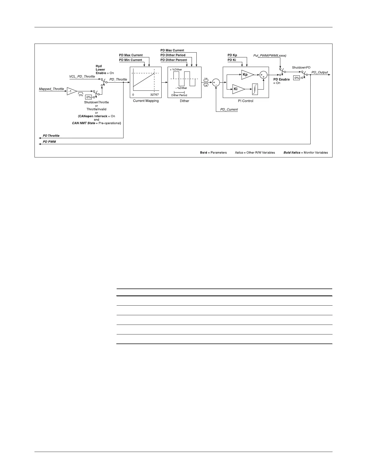
function. Note that Mapped_Throttle is inverted; lowering its value (making
it more negative) increases the PD_Throttle value.
The Dither function adds and subtracts from the current command to
the PD based on PD_Dither_Percent, at a rate set by PD_Dither_Period.
The dithered current command is compared to the present PD_Current
and the error is fed into a PI controller. The feedback gains are set by the param
-
eters PD Kp (proportional gain) and PD Ki (integral gain). The output of the
PI controller becomes the driver’s pulse width modulation, thus controlling the
average current of the driver. The final output is the VCL variable PD_Output,
which is displayed in the
1311 Monitor » Inputs menu as PD PWM.
The following PD processing variables are accessible by VCL:
VCL VARIABLE ACCESS DESCRIPTION
Mapped_Throttle Read Only Command from throttle section
VCL_PD_Throttle Read/Write VCL-accessible PD command
PD_Throttle Read Only Resultant command to the PD
PD_Current Read Only Average current flowing in the PD
PD_Output Read Only Resultant PWM at PD output
7 — VCL
Fig. 16 Proportional driver processing.