EasyManua.ls Logo

Universal Robots UR3/CB3 User Manual

Universal Robots UR3/CB3
256 pages
To Next Page IconTo Next Page
To Previous Page IconTo Previous Page
Page #152 background imageLoading...
Page #152 background image
13.12 Installation Features
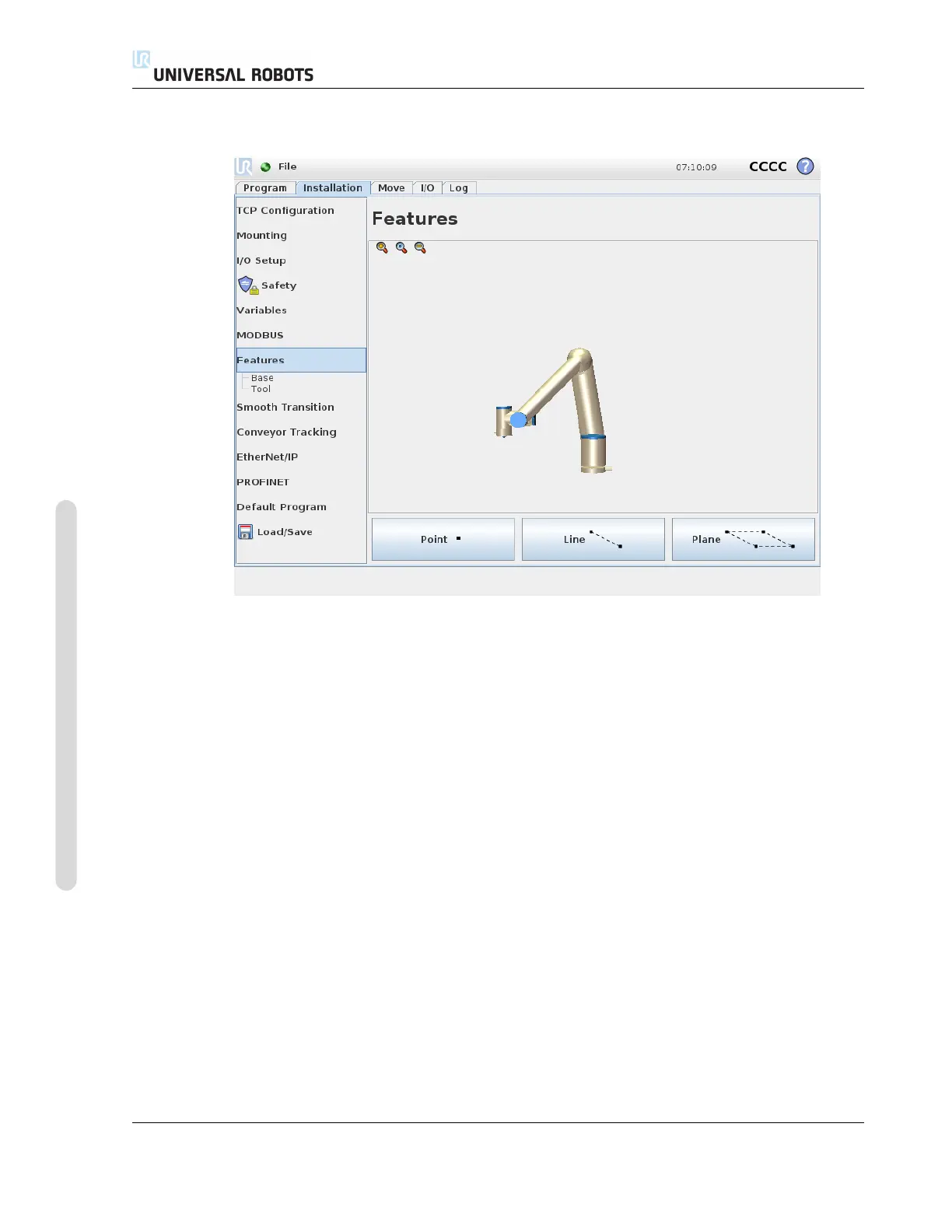
The Feature, is a representation of an object that is defined with a name for future reference and a
six dimensional pose (position and orientation) relative to the robot base.
Some subparts of a robot program consist of movements executed relative to specific objects other
than the base of the Robot arm. These objects could be tables, other machines, workpieces, con-
veyors, pallets, vision systems, blanks, or boundaries which exist in the surroundings of the Robot
arm. Two predefined features always exist for the robot. Each feature has its pose defined by the
configuration of the Robot arm itself:
The Base feature is located with origin in the centre of the robot base (see figure 13.1)
The Tool feature is located with origin in the centre of the current TCP (see figure 13.2)
User-defined features are positioned through a method that uses the current pose of the TCP in the
work area. This means the users can teach feature locations using Freedrive Mode or ”jogging” to
move the robot to the desired pose.
Three different strategies exist (Point, Line and Plane) for defining a feature pose. The best strategy
for a given application depends on the type of object being used and the precision requirements. In
general a feature based on more input points (Line and Plane) is be preferred if applicable to the
specific object.
To accurately define the direction of a linear conveyor, define two points of a Line feature with as
much physical separation as possible. The Point feature can also be used to define a linear conveyor,
CB3 II-54 Version 3.10
Copyright © 2009–2019 by Universal Robots A/S. All rights reserved.

Table of Contents

Question and Answer IconNeed help?

Do you have a question about the Universal Robots UR3/CB3 and is the answer not in the manual?

Universal Robots UR3/CB3 Specifications

General IconGeneral
Payload3 kg
Reach500 mm
Degrees of Freedom6
IP RatingIP54
Repeatability±0.1 mm
Power Supply100-240 VAC, 50-60 Hz
Protection ClassIP54
Weight11 kg
Base Footprint128 mm diameter
Max Speed1 m/s
Programming MethodGraphical programming interface
Communication InterfaceEthernet
Safety StandardsEN ISO 10218-1
Operating Voltage24 VDC

Summary

Part I Hardware Installation Manual

1 Safety

Essential safety information for robot installation and operation.

2 Safety-related Functions and Interfaces

Built-in safety functions and electrical interfaces for safe operation.

3 Transportation

Guidelines for safely transporting the robot arm and control box.

4 Mechanical Interface

Details on robot arm mounting, workspace, and payload specifications.

5 Electrical Interface

Information on controller I/O, tool I/O, Ethernet, mains, and robot connections.

6 Maintenance and Repair

Procedures and safety instructions for robot maintenance and repair tasks.

7 Disposal and Environment

Guidelines for robot disposal and environmental regulations compliance.

8 Certifications

Presentation of product certificates and declarations from test institutes.

9 Warranties

Manufacturer's warranty conditions and disclaimer information.

A Stopping Time and Stopping Distance

Data on robot stopping times and distances for safety analysis.

B Declarations and Certificates

EU Declaration of Incorporation and various third-party certificates.

C Applied Standards

Relevant standards applied during the development of the robot.

D Technical Specifications

Detailed technical specifications for the UR robot.

E Safety Functions Tables

Tables detailing safety functions, limits, and performance levels.

Part II PolyScope Manual

10 Safety Configuration

Configuration of robot safety system settings for workspace and personnel safety.

11 Begin programming

Guide to getting started with robot programming using PolyScope.

12 On-screen Editors

Overview of PolyScope's Expression Editor and Pose Editor screens.

13 Robot Control

Controlling robot movement via Move, I/O, MODBUS, and AutoMove tabs.

14 Programming

Detailed guide on creating and editing robot programs in PolyScope.

15 Setup Screen

Interface for initializing, updating, and configuring robot settings.

Part III EUROMAP 67 Interface

16 Introduction

Introduction to the EUROMAP 67 interface for IMM integration.

17 Robot and IMM integration

Information on integrating robots with Injection Moulding Machines (IMM).

18 GUI

Controlling the EUROMAP 67 interface through the GUI.

19 Installing and uninstalling the interface

Procedures for installing and uninstalling the EUROMAP 67 interface.

20 Electrical characteristics

Electrical characteristics of MAF light guard and I/O signals for IMM integration.

Related product manuals