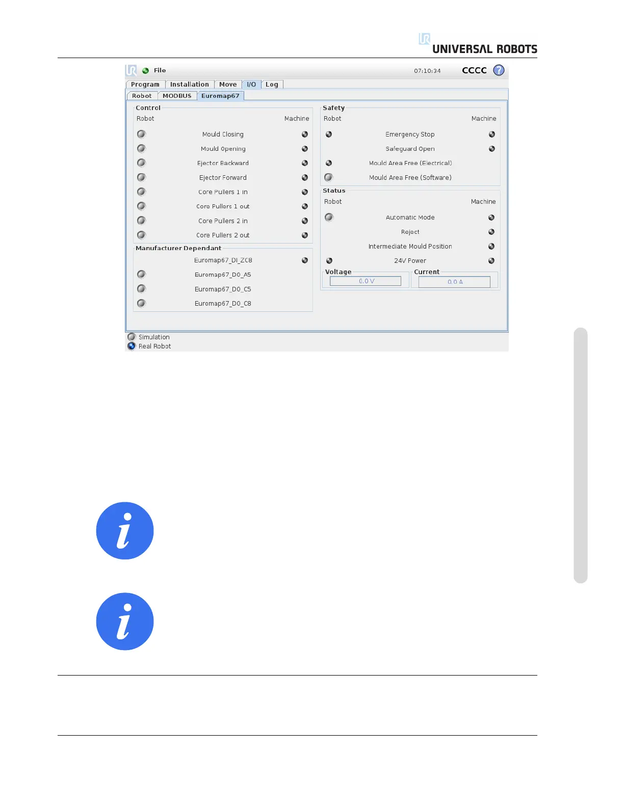
18.2 I/O overview and troubleshooting
There are four frames on this screen, which are described separately below. Common for all are the
two columns Robot and Machine, which respectively shows buttons for controlling output signals,
and indicators for showing state of input signals.
The (normal) state of the signals at startup, is that they are all low, except for the 24V signals, and
the robot output Automatic Mode which is active-low and therefore set high per default.
If a signal is not part of a program structure, and it is intended to be used in a robot program, this
is achievable making use of e.g. Action and Wait nodes.
NOTE:
“Automatic mode” from the robot to the IMM is active low. The but-
ton reflects the physical level and therefore “Automatic mode” is ac-
tivated when the button is not activated.
NOTE:
The buttons for controlling output signals are per default only avail-
abe in robot programming mode. This can, however, be set as desired
on the I/O setup tab found on the Installation screen.
18.2.1 Control
The signals related to controlling the interaction between the robot and the IMM are shown here.
These signals are all used by the program structures, where they have been joined in appropriate
Version 3.10
Copyright © 2009–2019 by Universal Robots A/S. All rights reserved.
III-13 CB3