5.3 Controller I/O
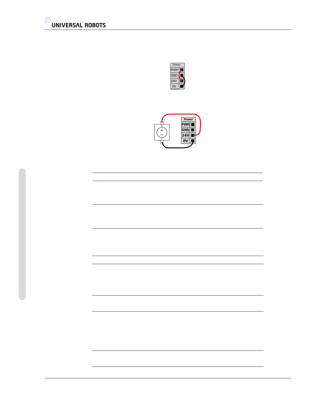
upper two (PWR and GND) are 24V and ground from the internal 24V supply. The lower two
terminals (24V and 0V) in the block are the 24V input to supply the I/O. The default configuration
is to use the internal power supply, see below.
If more current is needed, an external power supply can be connected as shown below.
The electrical specifications for both the internal and an external power supply are shown below.
Terminals Parameter Min Typ Max Unit
Internal 24V power supply
[PWR - GND] Voltage 23 24 25 V
[PWR - GND] Current 0 - 2 A
External 24V input requirements
[24V - 0V] Voltage 20 24 29 V
[24V - 0V] Current 0 - 6 A
The digital I/O are constructed in compliance with IEC 61131-2. The electrical specifications are
shown below.
Terminals Parameter Min Typ Max Unit
Digital outputs
[COx / DOx] Current* 0 - 1 A
[COx / DOx] Voltage drop 0 - 0.5 V
[COx / DOx] Leakage current 0 - 0.1 mA
[COx / DOx] Function - PNP - Type
[COx / DOx] IEC 61131-2 - 1A - Type
Digital Inputs
[EIx/SIx/CIx/DIx] Voltage -3 - 30 V
[EIx/SIx/CIx/DIx] OFF region -3 - 5 V
[EIx/SIx/CIx/DIx] ON region 11 - 30 V
[EIx/SIx/CIx/DIx] Current (11-30V) 2 - 15 mA
[EIx/SIx/CIx/DIx] Function - PNP - Type
[EIx/SIx/CIx/DIx] IEC 61131-2 - 3 - Type
UR3/CB3 I-32 Version 3.10
Copyright © 2009–2019 by Universal Robots A/S. All rights reserved.