APX 525/625 Generator Revision C Installation
©
2005 Del Medical Imaging Corporation
7/5/2005 Page 103
Table Image Receptor Connections
Connection Signal
Progeny
L/F 8000
L/F 9000
L/F 8000
(older models)
Villa
TB5-1
Table Select 117VAC
(Switched)
3 B3 7
TB5-2 Table Feedback 2 B2 12
TB5-3 117 VAC L B8 3
TB5-4 Signal GND 1 B1 11
TB5-5 117 VAC Return N B4 1
Chassis
GND
Chassis GND GND GND
Chassis GND
Note: For 120 VAC operation the Villa Bucky requires a jumper to be installed
between terminals 1 and 6).
If a grid cabinet or no image receptor will be employed, you must place a jumper
between TB5-4 and TB5-2 in order to allow exposures.
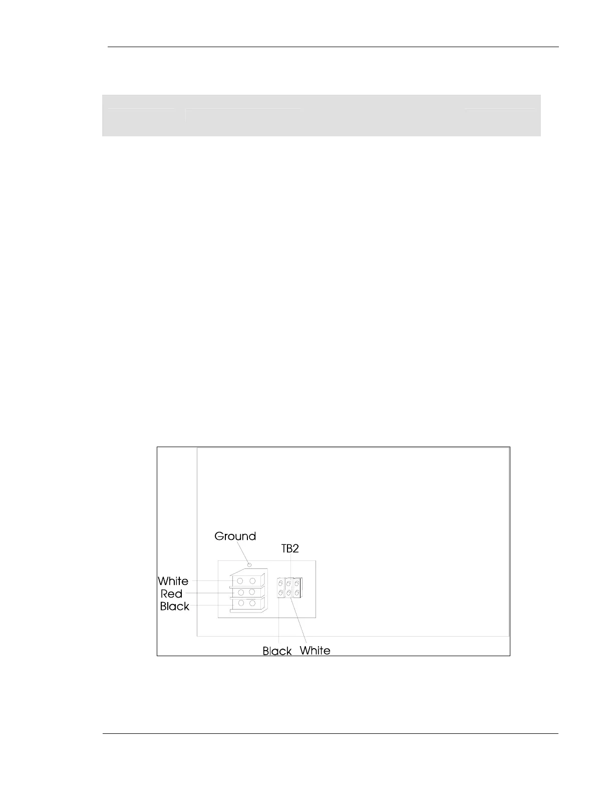
Connections from Line Match Transformer to Power Module
The wires shown below are from the line match transformer. See the pre-installation
planning section of this manual.
Figure 48 – Back of Power Module