APX 525/625 Generator Revision C Service Adjustments
©
2005 Del Medical Imaging Corporation
7/5/2005 Page 134
Calibrate mA
1. With power off, place the mA/Rotor Board on the extender card
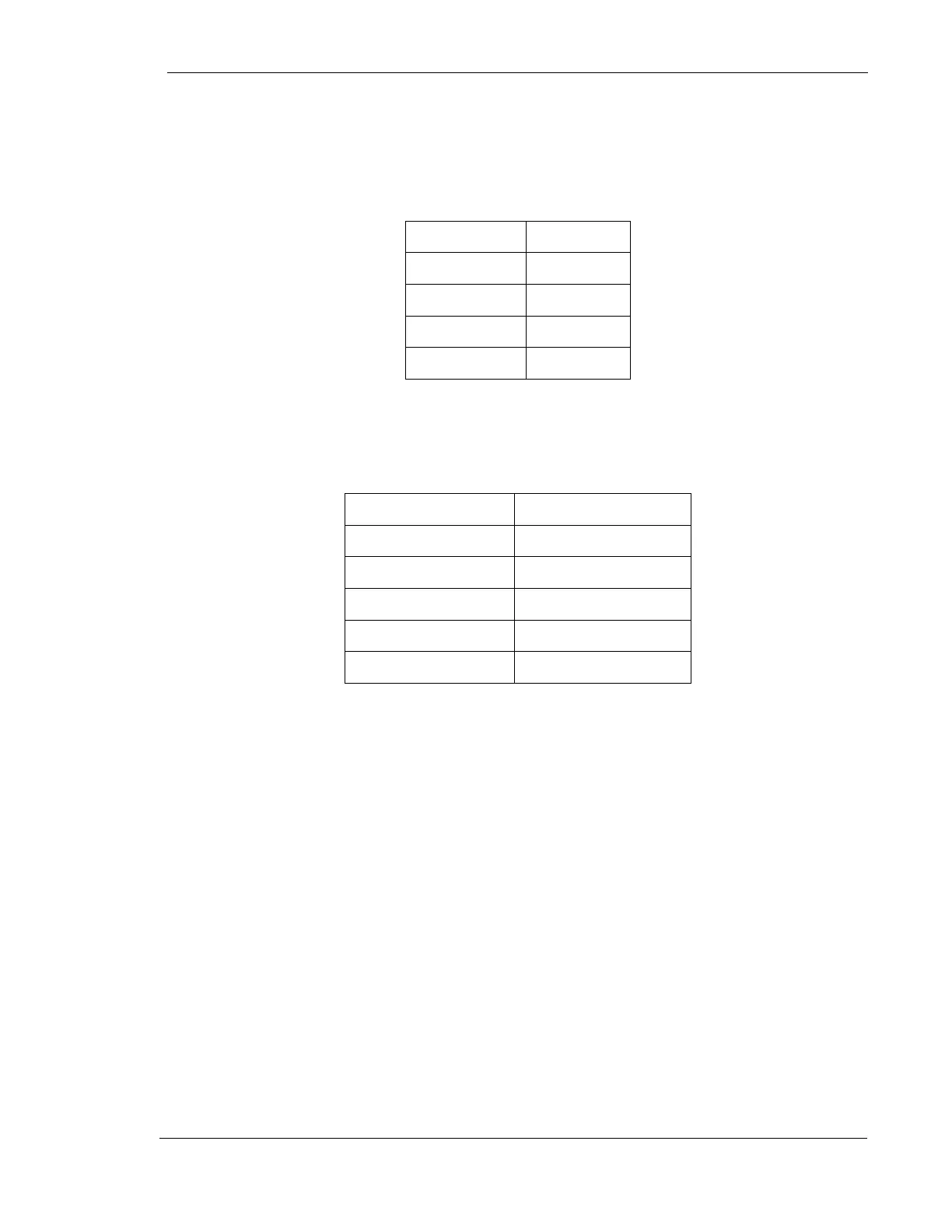
2. Turn power on. Set generator as follows:
Mode
3 Point
kV
84 kV
mA
300 mA
Focal Spot
Large
Time
100 mSec
3. For the initial mA calibration procedure, set up channel 2 of the scope to measure
the mA waveform, as in the table below:
Vertical Scale
100 mV / Division
Horizontal Scale
10 mSec / Division
Probe Scale
1X
Trigger
Positive
Mode
Normal Sweep
Storage
On
Make an exposure and note the actual mA of the exposure on the digital display.
Also note the voltage level at which the mA waveform on the scope stabilized during
the exposure.
The leading edge of the mA waveform for the large focal spot can be adjusted by
using pot R72 on the mA / Rotor Board. The mA at which the tube current should
stabilize following the initial portion of the exposure is adjusted with R63 on the
same board.
It may be necessary to make several exposures and perform several adjustments of
both pots, in order to obtain a flat, stabilized 300 mA (+/- 3 mA) waveform.