APX 525/625 Generator Revision C Service Adjustments
©
2005 Del Medical Imaging Corporation
7/5/2005 Page 126
15. Set the generator as follows:
a. Mode - 3 point
b. kV - 70kV
c. Time – 40 milliseconds
d. Focal spot - Large focus
16. Set the control to change “mA”. There are three commutating relays located
on the inner rear wall of the power module, two on the rear panel and K1 on
the inverter assembly. Notice the state of these relays in accordance with the
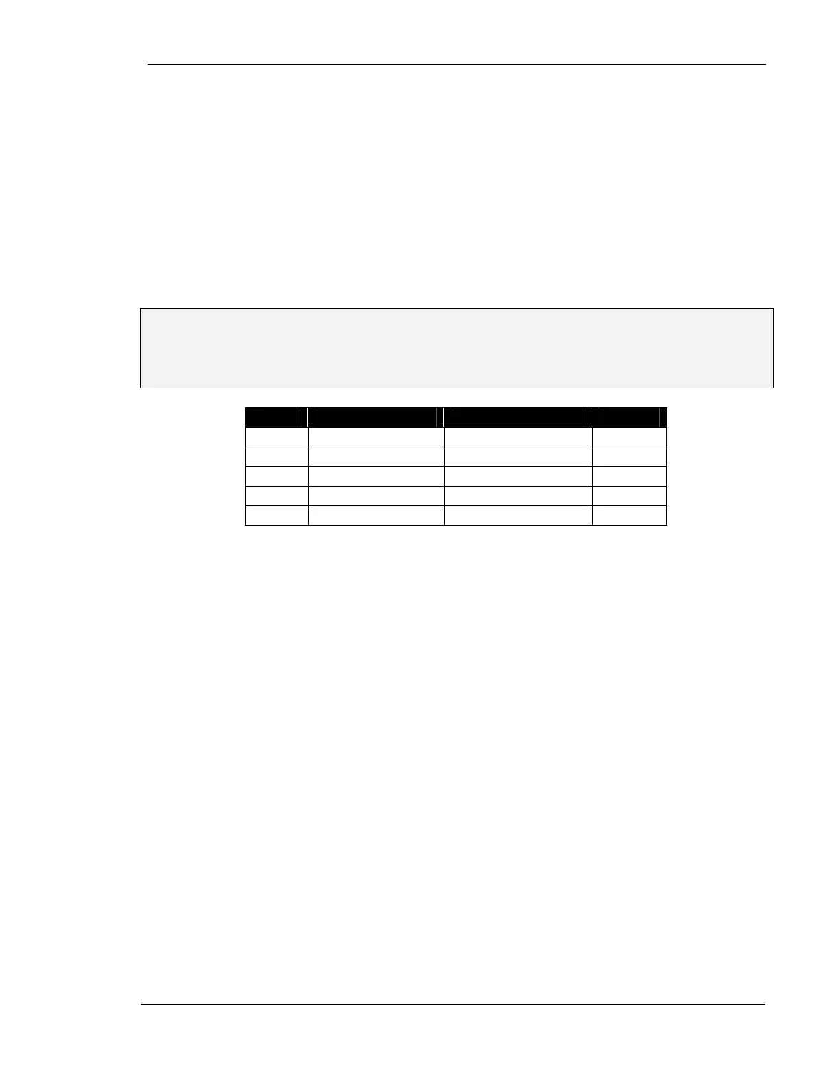
table below as "mA” is decreased
Note: Relay selection is X-Ray dependent. Actual relay combinations will vary
depending on the type of x-ray tube used in the unit. The following table is for a
30kW unit fitted with a Toshiba UX-51H42 X-Ray tube. Visual confirmation of
individual relay operation, not combination, is the goal of the following steps.
mA Left Panel Relay Right Panel Relay K1
400 Open Closed Open
300 Closed Open Closed
250 Closed Open Open
200 Open Open Closed
150 Open Open Open
17. Select small focus, verify that K11 on the I/O board is energized
18. Select large focus, verify that K11 on the I/O board is de-energized
19. Turn power "OFF"
20. Reconnect stator cable
21. Reconnect filament cable
22. Reconnect high voltage primary cable
23. After ensuring that no voltage is present on the capacitor bank, replace
the inverter fuse F1
Programming the Default System Configuration Menu
It is necessary to configure portions of the APX 525/625 operational software. During
the installation process, the installer must identify any installed components:
• X-Ray Tube Selection
• Accessories
• Default power derating settings
 Loading...