APX 525/625 Generator Revision C Operating Manual
©
2005 Del Medical Imaging Corporation
7/5/2005 Page 19
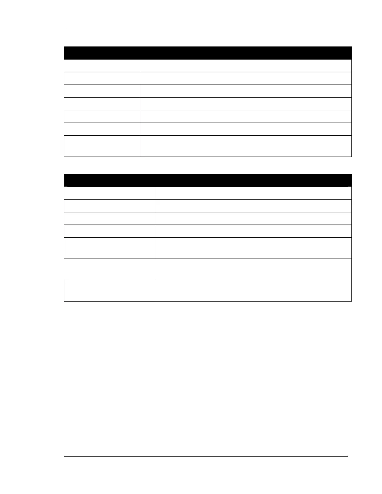
POWER MODULE
Power Rating 30 kilowatts or 40 kilowatts
Type High Frequency switch mode, Microprocessor Controlled
Kilovolt Range 40-125 kV
Maximum mAs 500 or 600
Minimum mAs 1.0
Maximum mA 500 or 600
Focal Spot Selection Operator Selectable Independent of Techniques (within Tube
Limits)
OPERATOR CONSOLE
mAs Increments Changes by factor of 1.2 per station
kV Increments 40 to 125 in one kV steps.
Time Increments 10 milliseconds to 6 seconds, in 35 steps
mA Increments 25 to 500 or 600mA in 12 steps
Fault Indicator For kV, mA, communications, operator termination of
exposure and AEC errors
Instantaneous Tube
Limit
Any selectable technique will be within tube limits.
Anode Heat Calculator Displayed in percentage of tube heat capacity. Updated
in six second intervals.
AEC
Post Exposure Indicator Digital Readout of mAs
Film-Screen Selection Two Different Film-screen combinations
AEC Density Control 5 steps from 50% of original value to 150% of original
value
Fault Indicator For backup mAs and Generator Termination
kV/Density optical tracking
kV range Phantom thickness Density +/-
40-54 4 inches (10.16 cm) .2 OD (Optical Density)
56-70 6 inches (15.24 cm) .2 OD (Optical Density)