APX 525/625 Generator Revision C Service Adjustments
©
2005 Del Medical Imaging Corporation
7/5/2005 Page 149
Additional Optional Inspections
The following four calibrations are not normally required. Information is included in
case they must be done.
Calibrate High Tension Transformer Balance
1. Connect Channel 2 of the scope to the Dynalyzer™ "C" BNC jack and connect
Channel 1 of the scope to the Dynalyzer™ "A" BNC jack.
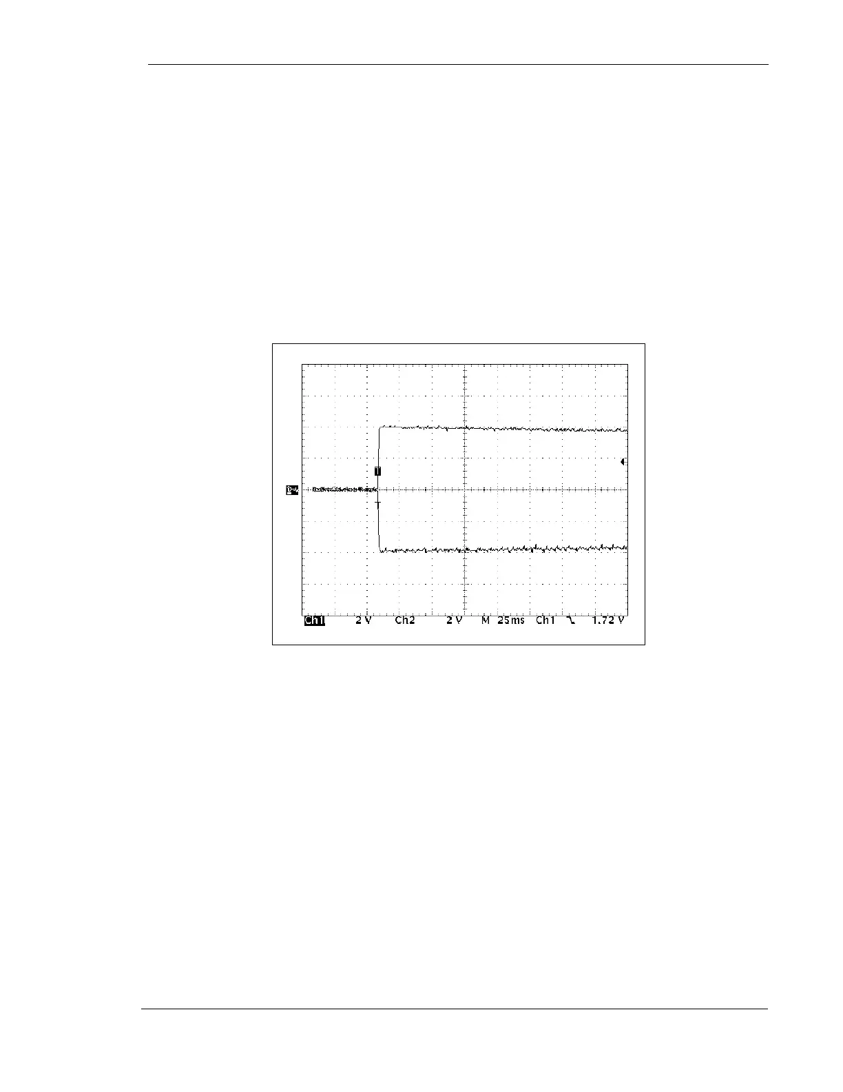
2. During the following adjustment observe the anode and cathode waveforms to
verify that the Dynalyzer™ is not reading spikes.
Figure 73 – Typical kV Waveform
Make an exposure and move the center tap of the power resistor on the back of the
power module until the Dynalyzer™ reading of Anode kV is the same as the reading
of Cathode kV.
Calibration of SCR Hold Off Time
This is a dead band adjustment that inhibits the cross firing of the SCRs.
1. With the generator power off, place the kV Regulator Board on the 024-0110G1
extender card.
2. Connect Channel 1 on a storage oscilloscope to pin 10 of U3 on the kV
Regulator Board.
3. Set up the scope as follows: