APX 525/625 Generator Revision C Service Adjustments
©
2005 Del Medical Imaging Corporation
7/5/2005 Page 156
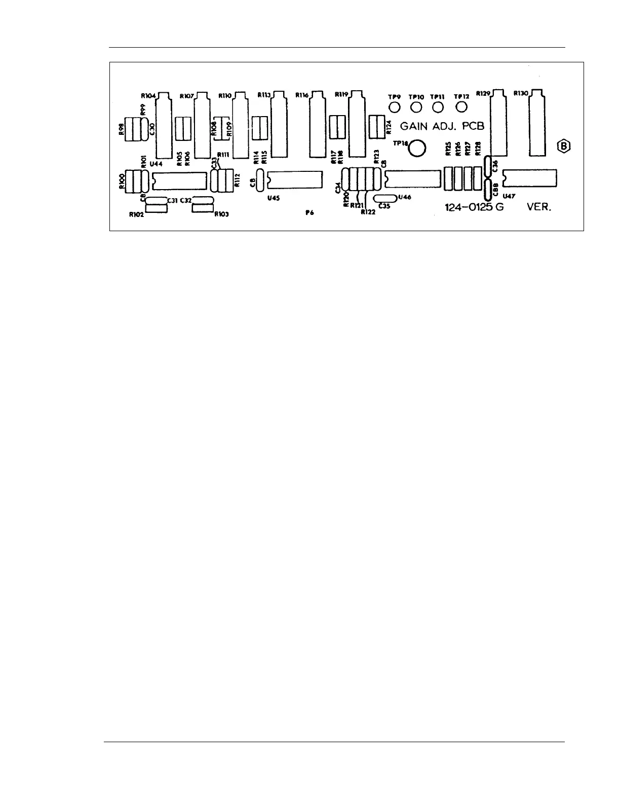
Figure 75 - Gain Adjustment Board
Preliminary Gain Adjustments
For the Table Image Receptor
1. Disconnect table ion chamber cable from main AEC board
2. Place a jumper from TP2 to TP15 (both on Main AEC Board)
3. Connect voltmeter to TP11 (on Gain Adjust Board) and Ground (of the Main AEC
Board)
4. Adjust R107 for 1.5 VDC
5. Remove the jumper and voltmeter. Reconnect ion chamber cable
For the Wall Image Receptor
1. Disconnect the wall ion chamber cable from the main AEC Board
2. Place a jumper from TP3 to TP15 (both on the main AEC Board)
3. Connect a voltmeter to TP10 (on the Gain Adjust Board) and ground
4. Adjust R113 for 1.5 VDC
5. Remove the jumper and voltmeter. Reconnect the wall ion chamber cable