APX 525/625 Generator Revision C Installation
©
2005 Del Medical Imaging Corporation
7/5/2005 Page 99
Modifications
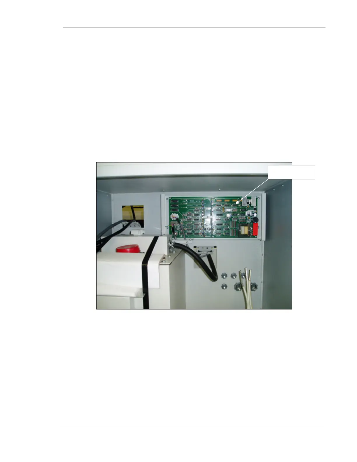
AEC Chassis Modifications
Once mounted in the rack cabinet, the rear mounting panel and the front box cover
of the AEC device will not be needed. The AEC control box assembly will mount
directly to the rear of the cabinet wall.
A circuit board retainer assembly will be added to fasten the kV Compensation Adjust
and the Gain Adjust boards in place. Assemble the retainer as shown below. All
necessary parts are included with the rack cabinet hardware.
Figure 45 – Mounting the AEC Control Box
Line Match Transformer
The line match transformer will be attached directly into the cabinet base. See the
“Equipment Placement” section of this manual.
AEC Device