APX 525/625 Generator Revision C Diagnostics
©
2005 Del Medical Imaging Corporation
7/5/2005 Page 173
To eliminate the HV Cables and X-Ray tube as the problem, try a No Load Test, as
described below.
No Load Test
1. Turn power to the generator off
2. Remove F3 on Power Supply PCB
3. Remove the Anode and Cathode high voltage cables from the High Voltage
Transformer and add a small amount of transformer oil (fill the cable sockets half
way for high kV tests) to prevent arcing
4. Connect a scope to the kV Feedback test points (TP10, TP11, TP12-GND on
Motherboard 124-0106G1)
5. Turn power to the generator on and set a low power technique on the control
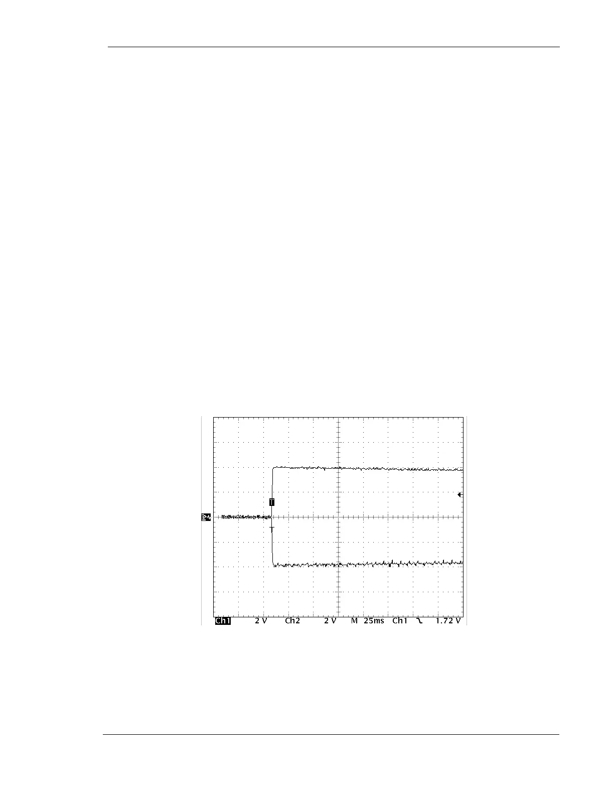
6. Make an exposure and observe the kV waveform. The unit should initiate an
exposure and make a ticking sound, due to the slow running speed of the
inverter under no-load conditions. The exposure will continue until the button is
released. At that time a “Button Fault” should be displayed. The usual high
frequency sound will not be heard upon PREP. The kV waveform should be
balanced (anode to cathode) and accurate but the ripple will be a very low
frequency and greater in amplitude than normal
Figure 3: Typical No-Load Waveform