APX 525/625 Generator Revision C Service Adjustments
©
2005 Del Medical Imaging Corporation
7/5/2005 Page 150
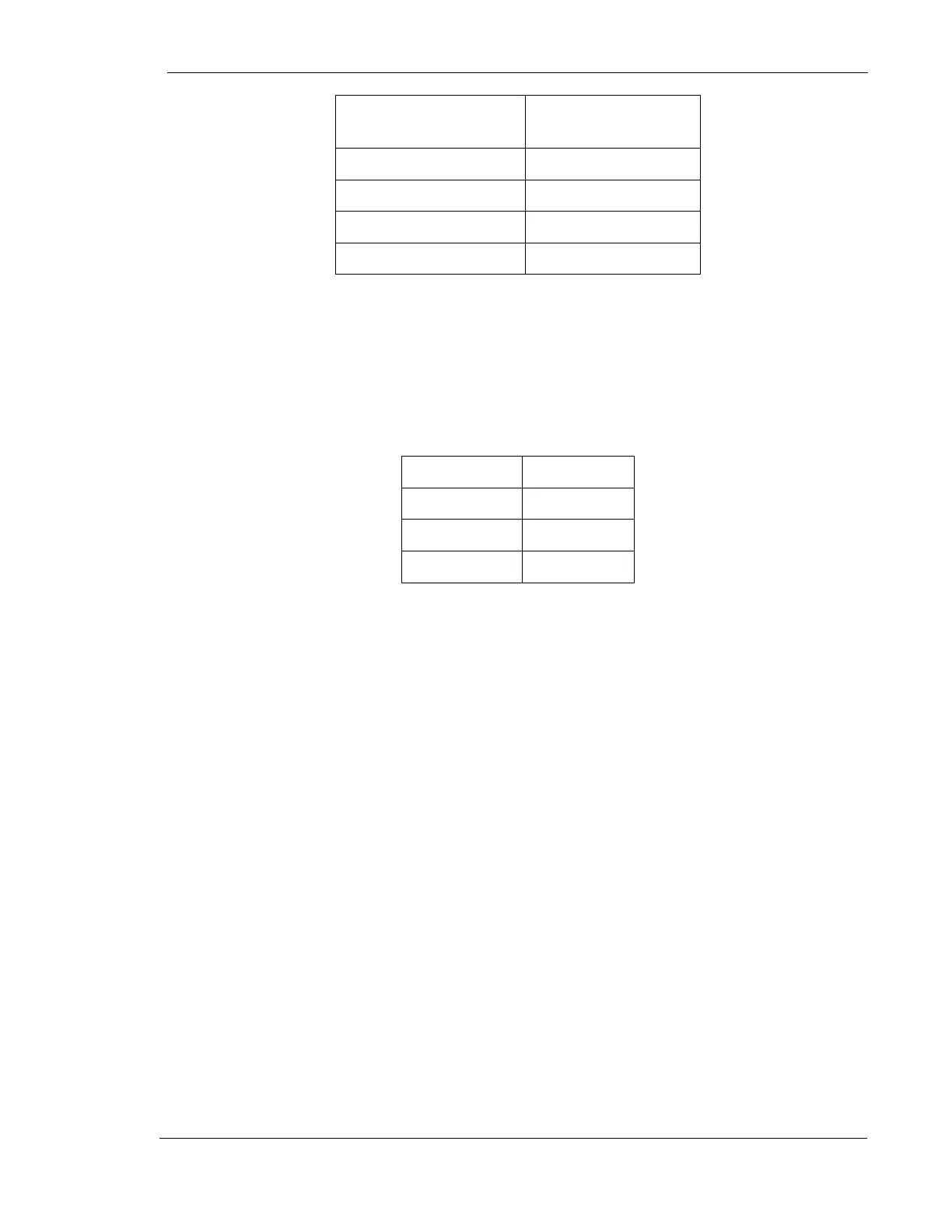
Channel 1 Vertical
Scale
5 V / Division
Horizontal Scale
20 µSec / Division
Mode
Single sweep
Trigger
Channel 1
Polarity
Negative
4. Set up the generator as follows:
Mode
2 point
Focal Spot
Large
kV
80 kV
mAs
31 mAs
5. Make exposure and adjust R65 on the kV Regulator Board 124-0110G1 so that
the negative portion of the waveform is 140 µSec (-0, +10 µSec).
6. Turn the generator OFF.
7. Remove the kV Regulator Board from the card extender and return it back to its
original position in the card cage.
Boost Time Adjustment
1. Place the mA/Rotor board on the extender card.
2. Attach scope probe to TP1 on the mother board, ground clip to ground test point
on the mother board.
3. Set scope time base for .5 seconds per division. Vertical deflection for 2 volts per
division.
4. Turn controller ON.
5. Press "PREP”. Observe the rotor boost time. Adjust (if necessary) R29 of the
mA/Rotor board to provide 1.5 seconds of rotor boost.
6. Turn controller OFF.
7. Remove mA/Rotor Board from the extender card and restore it to its original
position in the card cage.