APX 525/625 Generator Revision C Operating Manual
©
2005 Del Medical Imaging Corporation
7/5/2005 Page 18
Specifications
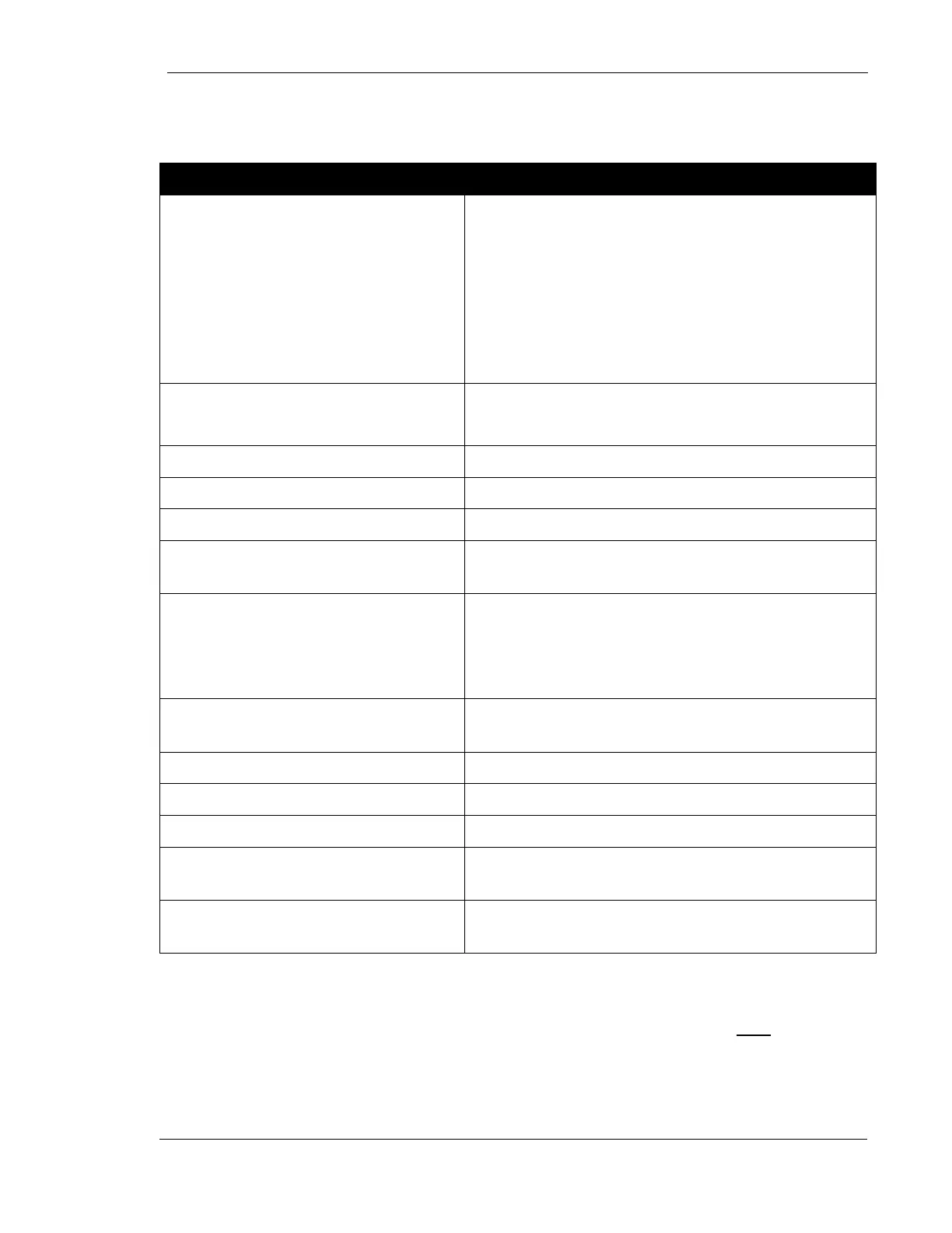
GENERAL
Input Power
(Note: APX 625 operates only on
three phase)
208 VAC, 60 Hz., single phase, maximum
momentary current draw: 366 Amps
240 VAC, 60 Hz., single phase, maximum
momentary current draw: 293 Amps
or
208 to 480 VAC, 60 Hz, three phase (consult
pre installation chapter for specific currents
Maximum power technique
APX 525: 60 kV, 500 mA, 100 mSec (50 mAs)
APX 625: 60 kV, 600 mA, 100 mSec (60 mAs)
Line regulation +/- 7 percent
Duty Cycle 1 Percent
kV Selection 40 to 125 kV in increments of 1 kV
kV Accuracy
Indicated value +/- (3 kV + 3 Percent of (Note
1) indicated value)
mAs Selection
APX 525: 1→500 mAs, increments of 1.2 x
previous value
APX 625: 1→600 mAs, increments of 1.2 x
previous value
mAs Accuracy
1
Indicated value +/- (.6 mAs + 5 Percent of
indicated value)
mA Accuracy
2
+/- (5mA + 5% of indicated value)
Time Selection
2
10 milliseconds to 6 seconds, in 35 steps
Time Accuracy
2
Indicated value +/- (15% + 5 mS)
Technique Factor Max Line
Current
100 kV, Large Spot, 32 mAs
Regulatory
Meets the requirements of 21 CFR
Sub-Chapter J.
1
On some combinations of kV and mAs there may be a single 2 millisecond kV
overshoot of up to 10% at the beginning of the exposure.
2
mA and Time may be specified by the operator in the 3 point mode only.
Note: In 2 point mode, at low kV and mAs (less than 5 mAs) the pre-indicated time
may vary from the actual time by 50%. Since the radiation output is determined by
kV and mAs only, the pre-indicated time has no direct effect on the actual exposure
dose.