APX 525/625 Generator Revision C Service Adjustments
©
2005 Del Medical Imaging Corporation
7/5/2005 Page 139
Mode
3 point
Tube
1
Focal Spot
Large
kV
80
mA
200 mA
Time
100 mSec
4. Connect channel 1 to the anode BNC output of the Dynalyzer™
5. Connect channel 2 to the cathode BNC output of the Dynalyzer™
6. Set up the oscilloscope as follows:
Channel 1 Vertical Scale
2V / Division
Channel 2 Vertical Scale
2V / Division
Horizontal Scale
10 mSec / Division
Trigger
Channel 1
Polarity
Positive
Mode
Normal
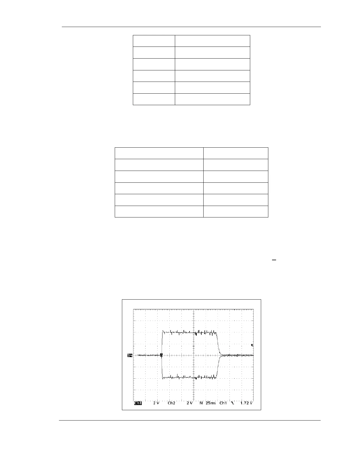
7. Adjust the baseline position of the two channels so that they are both aligned on
the same centerline of the vertical scale. Channel 1 will display the positive
anode kV at 20 kV / division, and channel 2 will display the negative cathode kV
at 20 kV / division
8. Make exposure and adjust R77 on kV Board for 80 kV (+1 kV) on the
Dynalyzer™ digital display. Verify that the anode and cathode waveforms are of
nearly equal amplitudes, and that the sum of the two voltages equals 80 kV (+8
VDC differential voltage on the oscilloscope)
Figure 68 – kV Waveform