APX 525/625 Generator Revision C Service Adjustments
©
2005 Del Medical Imaging Corporation
7/5/2005 Page 142
Warning: Observe proper radiation protection procedures because the following steps
will produce x-ray emissions.
7. Select 250 mA and make an exposure. Observe the mA wave form on the
oscilloscope. The waveform should achieve stabilization at +5 VDC.
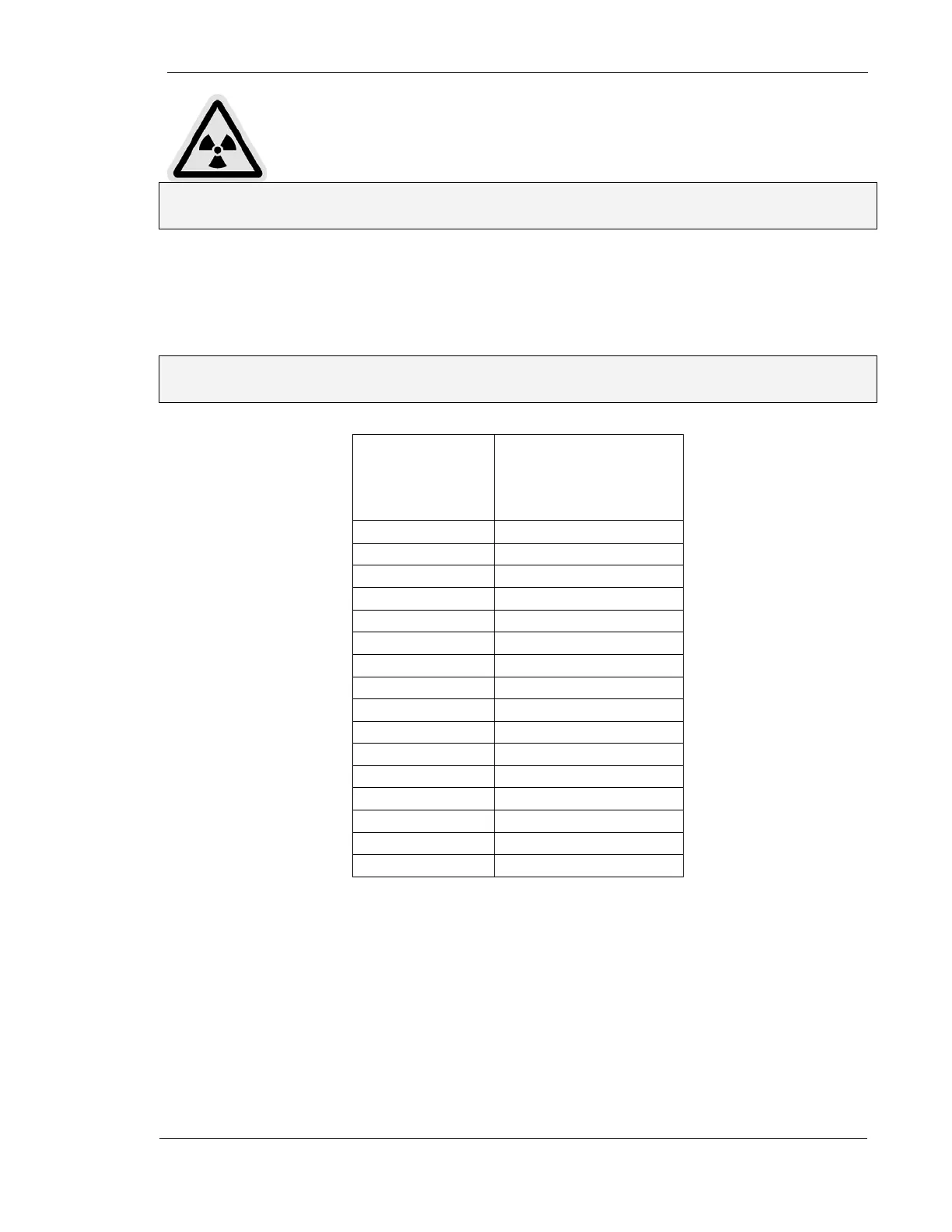
8. You may also use the information in the table below to predict the amplitude of
the waveform for other mA values:
Note: Exposure time can be adjusted to allow the predicted mA to match up with the
chart.
Selected mA
mA amplitude
(equivalent voltage
across TP14, mA+
and TP13, mA-)
25 +0.5 VDC
50 +1.0
75 +1.5
100 +2.0
150 +3.0
200 +4.0
250 +5.0
300 +6.0
350 +7.0
400 +8.0
450 +9.0
500 +10.0
550 * +11.0
600 * +12.0
650 * +13.0
700 * +14.0
* Available on 40 and 50 kW generators only
9. Make an exposure and observe the waveform. If necessary, adjust R63 on the
mA/Rotor Board, so that the waveform stabilizes at +5 VDC for 250 mA.
10. When the waveform stabilizes at the proper voltage, adjust R72 (Tube 1, Large
Focus Preheat) on the mA/Rotor Board for an overall flat waveform