APX 525/625 Generator Revision C Service Adjustments
©
2005 Del Medical Imaging Corporation
7/5/2005 Page 153
1. With the power "OFF" place a jumper on the AEC device "Main AEC Board"
between the ground lead and TP6
2. Turn the generator "ON", select Manual, then select AEC operation
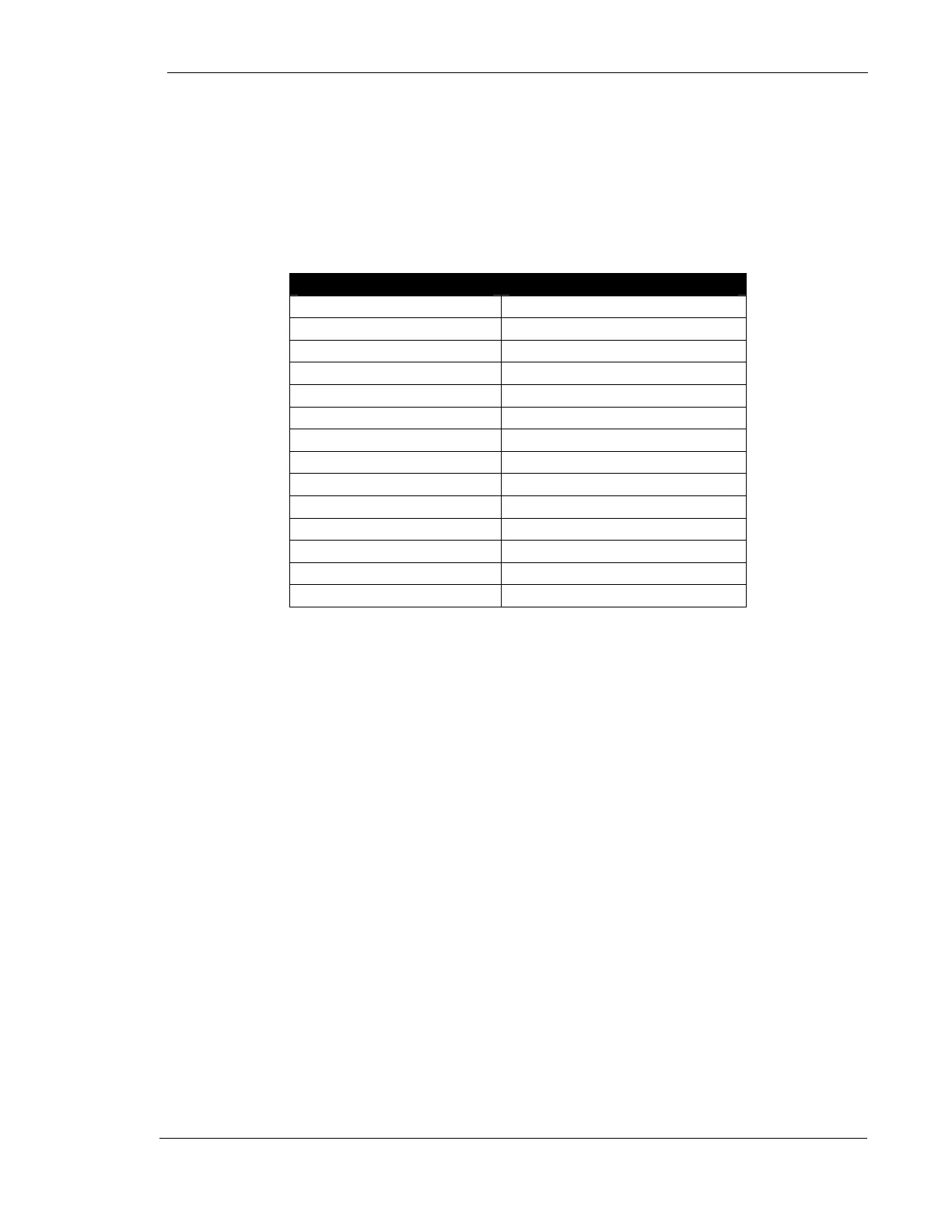
3. Move through the selections on the chart below, verify that the proper LED's
illuminate
Control Selection LED on Main AEC Board
Left field 2
Center field 3
Left and Center fields 2 and 3
Right and Center fields 3 and 4
All fields 2,3 and 4
Left and Right fields 2 and 4
Right Field 4
Screen One LED 5 on
Screen Two LED 5 off
Density Normal 6
Density -25% 7 and 8
Density -50 7
Density +25% 6 and 8
Density +50% 6 and 7
4. Turn the generator "OFF", remove the jumper.
5. Place a jumper on the Main AEC Board between TP8 and the ground point on
the same board.
6. Turn the generator on, select AEC, 2-point large spot. See the chart on the next
page for typical LED sequencing.
7. Each change you make in the kV level will result in a corresponding change in
the pattern of the LEDs on the AEC board (see the chart on the next page). If
there is no change in the pattern, call Technical Support at 847-288-7000.
8. Turn the generator OFF.
9. Remove the jumper between TP8 and ground.