APX 525/625 Generator Revision C Diagnostics
©
2005 Del Medical Imaging Corporation
7/5/2005 Page 167
• a defective X-ray tube
• high voltage cables
• faulty high-tension transformer
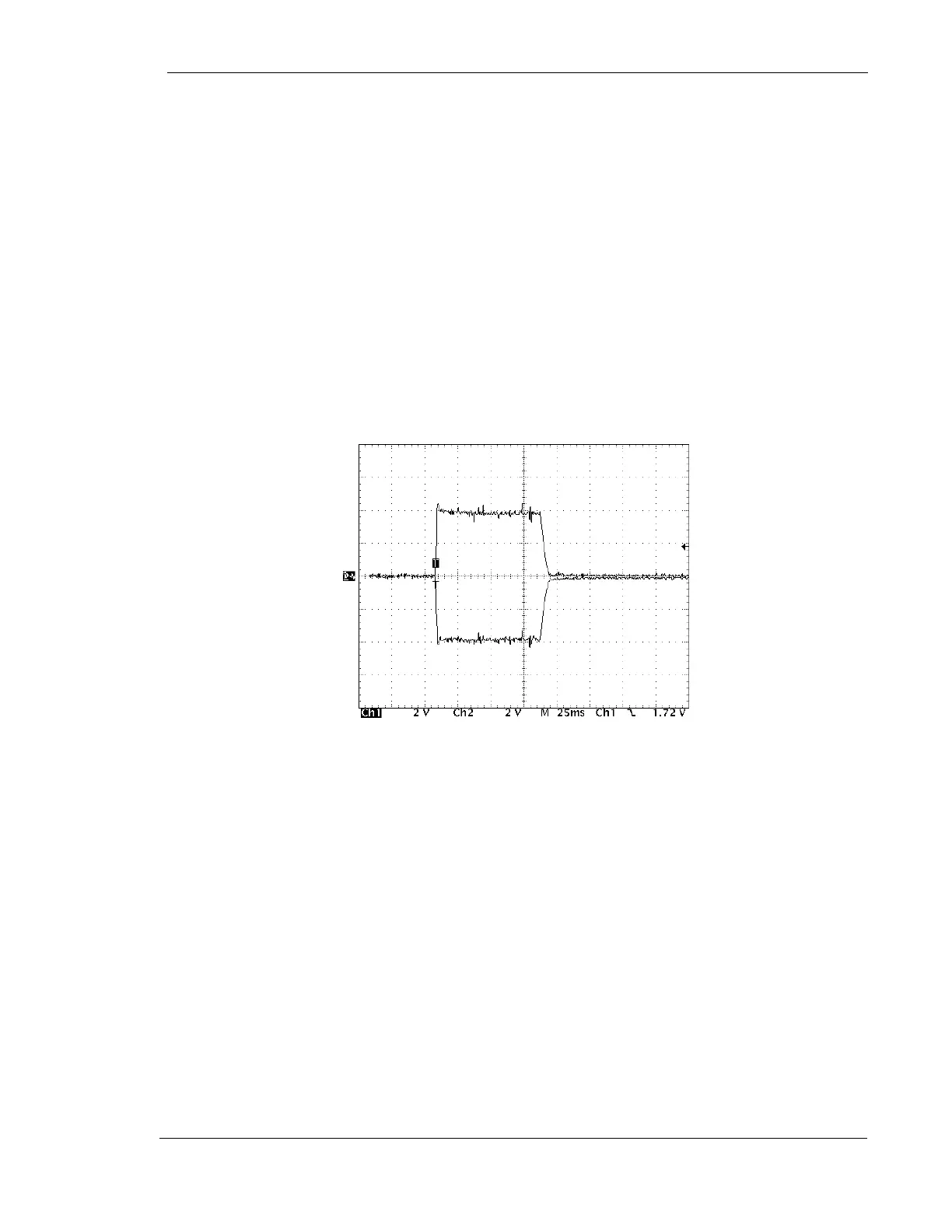
1. Connect 2 channels of an oscilloscope to kV+/- to TP-12 on the motherboard
2. Make an exposure. Based on a voltage interpretation of 1V=10kV, the anode and
cathode waveforms should be equal in amplitude. See Figure 1, ”Proper kV
Balance Anode to Cathode”
3. Turn power off to the generator and try to balance the anode and cathode by
adjusting the balance resistor located on the rear side of the power module,
behind the screened box
4. Turn on the generator and make an exposure. Take note of the change and
repeat step 3 as necessary
Figure 1: Proper kV Balance - Anode to Cathode
5. If adjustment is not possible, check to see if the imbalance still occurs during a
No-Load test. See “No-Load Test” later in this section. If the imbalance persists,
the high-tension transformer is probably defective
Check for a loss of 26 VDC at the power supply board that supplies the SCR
gate transistors on the kV Regulator Board
1. Turn power off to the generator
2. Place the kV Regulator board on an extender card
3. Connect a voltmeter positive lead to the anode of CR-5 and the negative lead to
the anode of CR3
4. Turn-on the generator and measure the voltage which should be approximately
26 VDC