APX 525/625 Generator Revision C Diagnostics
©
2005 Del Medical Imaging Corporation
7/5/2005 Page 170
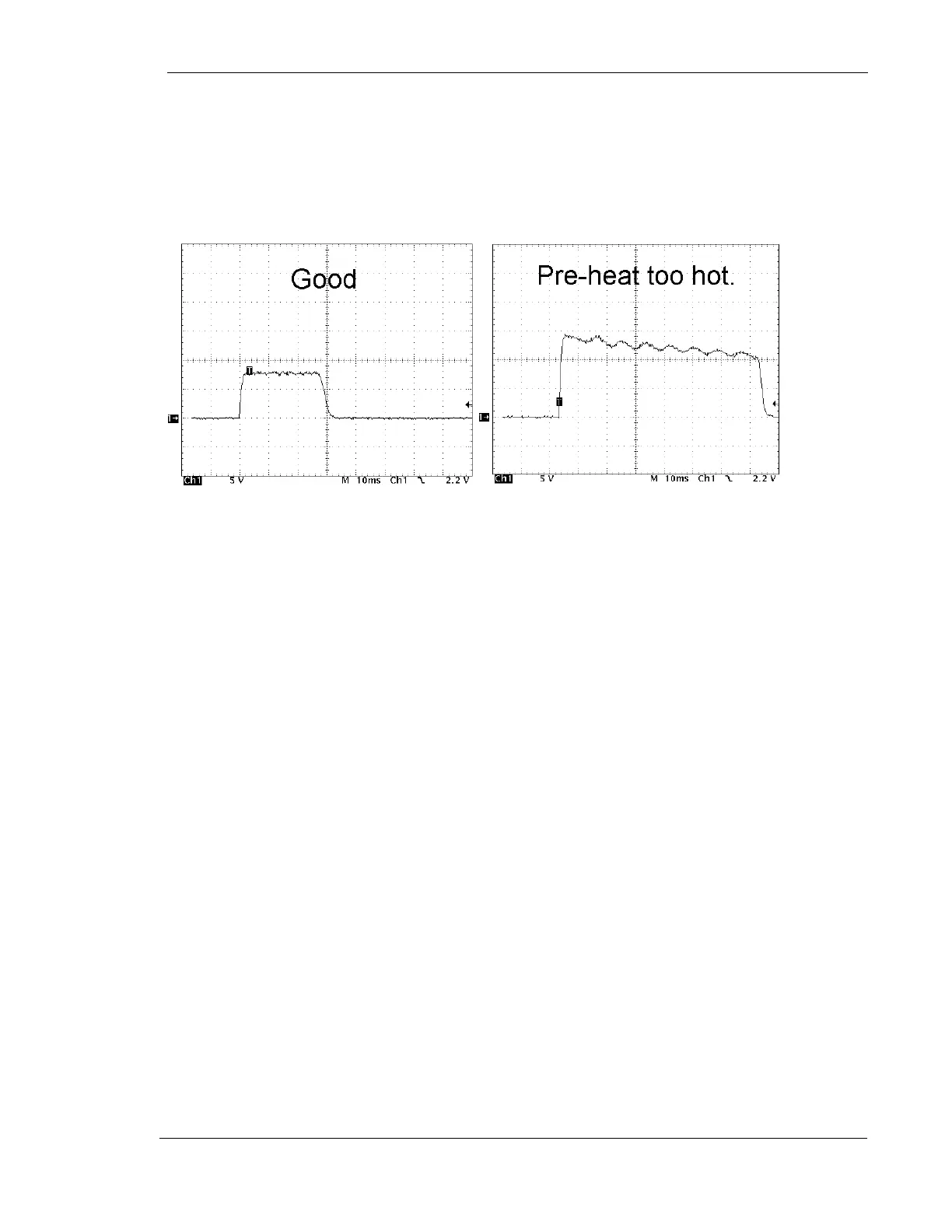
7. If the waveform is not flat, adjust R72 as necessary. See Figure 2, ”Example of
Pre-heat Wave-forms”
8. Select the Small focal spot and make another exposure. Adjust R70 as
necessary
Figure 2: Example of Preheat Waveforms
9. Note the amplitude of the waveform and adjust R63 if necessary
Refer to the mA calibration section of this manual for details.
Check for a power line input dropping below 235VAC during an exposure
1. Measure incoming line voltage at the line contactor input of the inverter power
supply with an oscilloscope set up for differential voltage measurements
2. Take note of the voltage during a full power exposure (60kV, 100 mAs, Large
Spot). If the level drops dramatically, then the power line is unstable, or the
wrong wire size may have been used
Check for a poor conducting high voltage cable
1. Turn OFF power to the generator
2. Remove high voltage cables from both the high-tension transformer and X-ray
tube
3. Check to make sure the cable pins are sufficiently spread to make good contact
4. Reconnect the cables
If problems persist, turn power off to generator and temporarily swap the anode and
cathode cables with each other at both ends.
Check for excessive ripple on the DC rail voltage due to a defective filter
capacitor or defective diode pack