APX 525/625 Generator Revision C Pre-Installation
©
2005 Del Medical Imaging Corporation
7/5/2005 Page 48
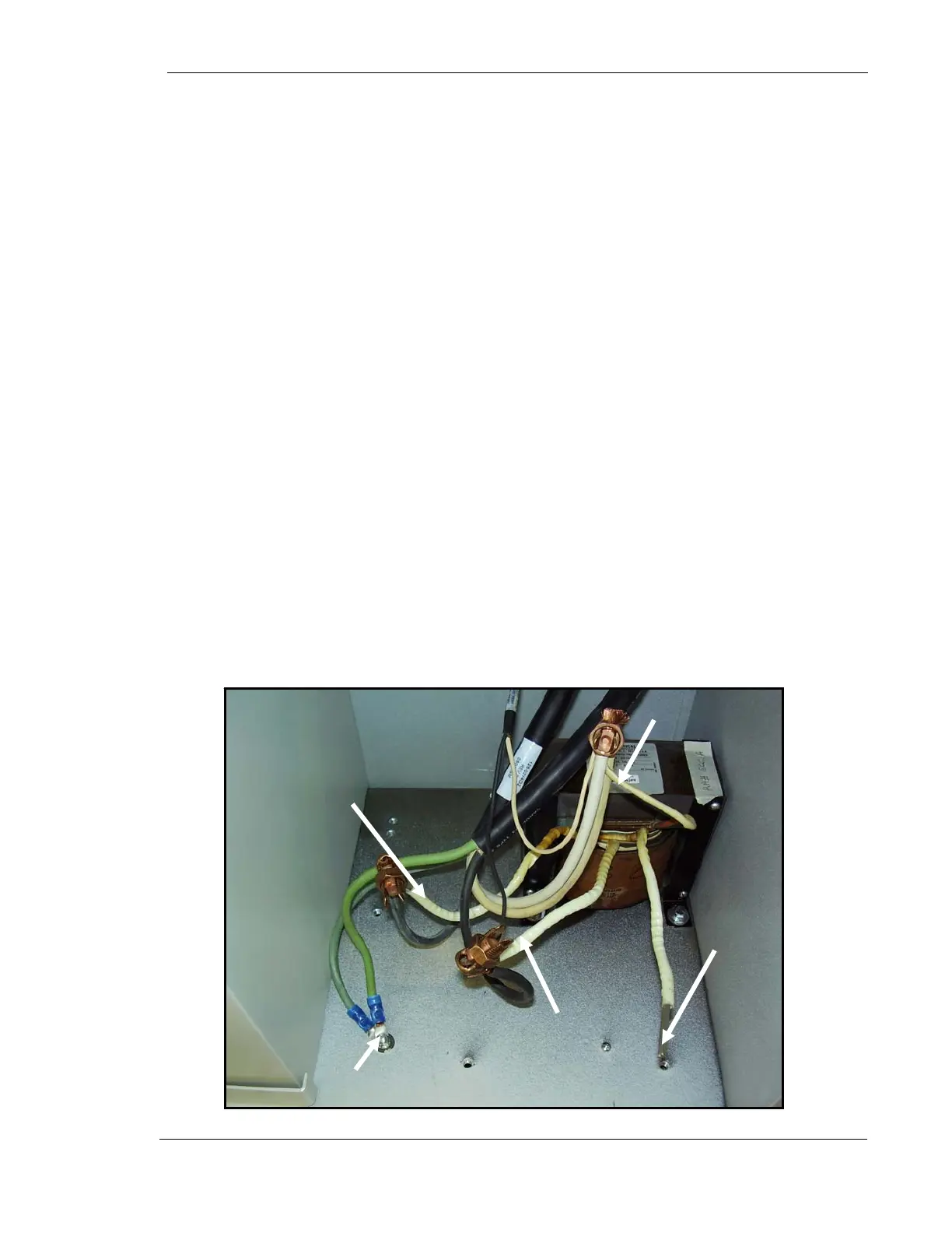
30. Connect one of incoming incoming 240 VAC power lines to lead # 1 on in-
line transformer with Burndy connector as shown in Figure 14 below. Do
not wrap connection with tape yet.
31. Connect other incoming incoming 240 VAC power line to lead # 3 on in-
line transformer with Burndy connector as shown in Figure 14 below. Do
not wrap connection with tape yet.
32. Wrap end of lead #2 with electrical tape to securely insulate it. This lead
will not be used
33. Connect lead #1 on line matching transformer to white wires from cables
126-0214G2 and 126-0211G1 with Burndy connector as shown in Figure
14 below. Securely wrap connection with electrical tape.
34. Connect lead #3 on line matching transformer to black wire from cable
126-0211G1 with Burndy connector as shown in Figure 14 below.
Securely wrap connection with electrical tape.
35. Connect lead #4 on line matching transformer to black wire from cable
126-0214G2 with Burndy connector as shown in Figure 14 below.
Securely wrap connection with electrical tape.
36. Connect green ground eyelet from cable 126-0214G2 and green ground
eyelet from incoming power line to ground lug as shown in Figure 14
below.
Procedure is Complete.
Figure 14. Transformer Connections
Lead #4
Lead #3
Lead #2
Lead #1
Ground E
elets