APX 525/625 Generator Revision C Pre-Installation
©
2005 Del Medical Imaging Corporation
7/5/2005 Page 67
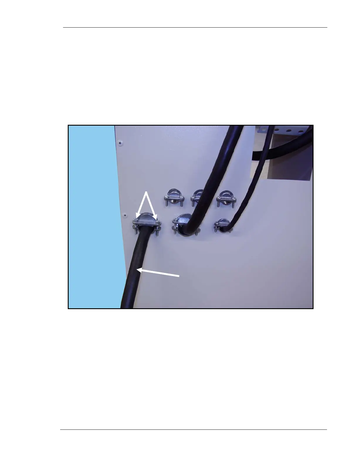
33. Loosen two stress relief clamp screws (1 Fig. 14).
34. Insert the end of the main power cable (2) into the stress relief clamp and
into the generator cabinet until there is enough wire slack inside the cabinet
for the cable wires to reach all tabs on the transformer. The outer insulation
on the cable should be stripped back to allow 12” (30cm) of internal wire
exposed. Each internal wire should have about ½” (10mm) of insulation
stripped from each end.
35. Tighten stress relief clamp screws.
Figure 14. Main Power Cable Stress Relief
36. Connect red, white and black wires from main cable to 208 VAC Burndies on
in-line transformer. It does not matter which color wire goes in which position.
Securely wrap each Burndy connection with electrical tape.
37. Connect ground wire to lug on bottom of cabinet.
2
1