APX 525/625 Generator Revision C Pre-Installation
©
2005 Del Medical Imaging Corporation
7/5/2005 Page 74
Figure 7. Proper Cable Position
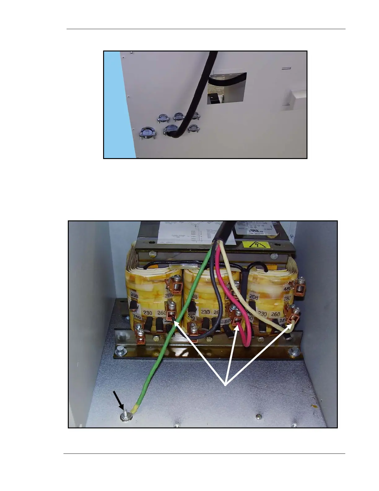
14. Connect red, white and black wires to (1,2 & 3 in Fig. 8) 280 VAC Burndies on
transformer as shown below. It does not matter which color wire goes in
which position. Securely wrap each Burndy connection with electrical tape.
15. Connect ground wire to lug (4 in Fig. 8).
Figure 8. Main Cable Connections
4
1, 2 & 3