Installation
February 2011 2-10 P/N 06-237041-001
To install the PMU Board into the top tier of an enclosure:
1. Make sure the control unit location is dry and that the enclosure is free of construction dust and
metal shavings prior to installing the PMU Board.
2. Remove the PMU Board from its packaging.
3. Orient the board such that its black AC power input connectors (TB1) are positioned at the top
right corner.
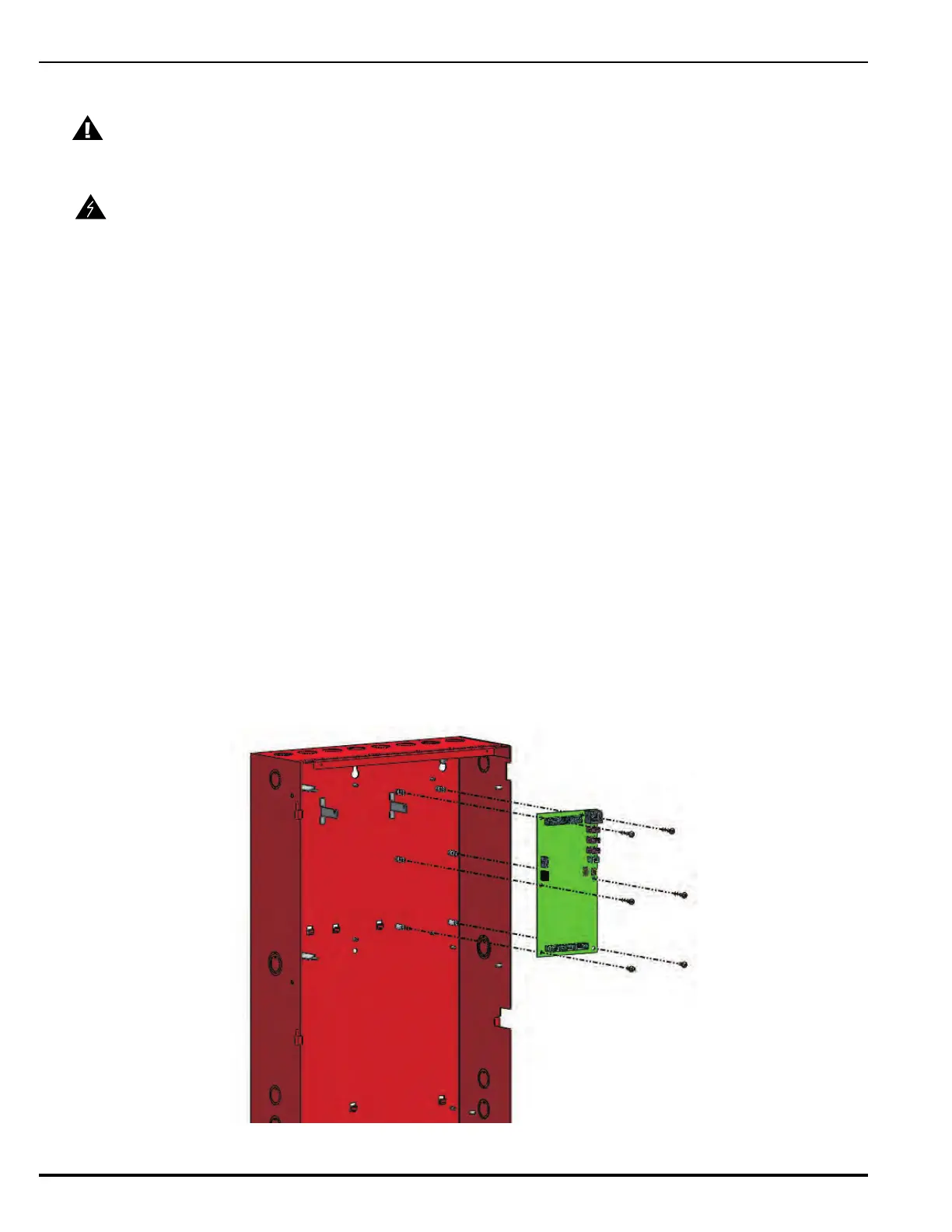
4. Locate the rightmost Power Supply Unit fastening tab in the enclosure’s back panel. Position the
PMU board such that the left side of the board aligns with this tab and the six mounting screw
holes (as shown in Figure 2-6).
5. Locate the six #8 Phillips-head mounting screws, 5/8-in. standoff and ground wire assembly
found in the hardware kit.
6. Insert and hand-tighten two of the three mounting screws on the left side of the board to hold it
in place and align screw holes.
7. Position the 5-in. ground wire assembly over the right topmost screw hole (located beside the
AC power input connector). Refer to Figure 2-12 for location of screw hole. Insert the 5/8-in.
standoff and mounting screw; hand-tighten.
8. Put all remaining mounting screws in place and tighten securely.
9. With the PMU board mounted, connect the wire harnesses from the power supply unit(s) to the
white connectors (J1 and J2) at the top of the board (as shown in Figure ).
10. Proceed to Section 2-4.6, Making AC Power Source and Earth Ground Connections.
Figure 2-6. Installing A PMU Board into the Enclosure Top Tier
CAUTION
Use a ground strap to prevent static discharge that could damage the PCB.
WARNING
Ensure that the dedicated AC circuit is shut off at its source before beginning this
procedure.
To ensure proper ground fault
detection, install all six (6)
mounting screws.
 Loading...