Appendix A. Wiring Diagrams
A.1 QML Data Logger Connector Block
The QML data logger includes:
• 10 measurement channels and one internal channel for pressure measurement
• 1 connector block for power supplies
• 1 connector block for communication channels
• 2 blocks for optional communication modules
Single-ended (H-C or L-C) or
dierential (H-L) measurements can be performed in the
10 measurement channels.
Each sensor in a basic setup has its own dedicated channel. For reference purposes, see
the following tables.
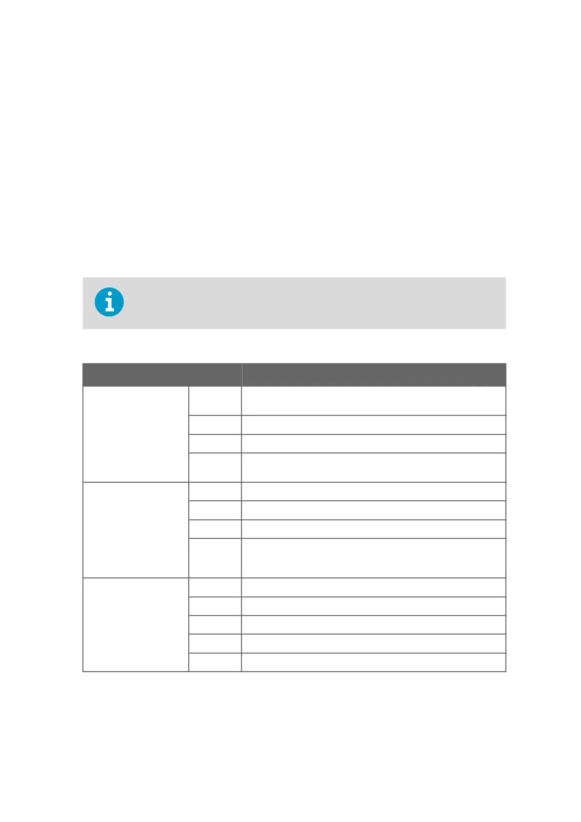
Table 14 Analog Measurement Channels
Channels Pin Name Description
CH0, CH1, CH2, CH3
24‑bit ADC
E 12 V / 25 mA voltage excitation ON/OFF where voltage can be
measured, or 100 μA / 1 mA current excitation.
H Analog input (high)
L Analog input (low)
C The pin has been connected to ground (GND) via a 10 Ω resistor so
that the current can be measured.
CH4, CH5, CH6, CH7
24‑bit ADC
E 100 μA / 1 mA current excitation
H Analog input (high)
L Analog input (low)
C Common return and reference level for voltage measurements via
the channel's own E, H, and L pins. The pin has been connected
directly to ground.
CHA, CHB
Suitable for fast-changing
input signals
12-bit ADC
F Frequency input with 10 Ω selectable pull‑up/pull‑down resistor
E 0 ... 12 V / 20 mA adjustable excitation voltage, can be measured
H Fast analog input (high)
L Fast analog input (low)
C Common return (analog ground)
Appendix A – Wiring Diagrams
237

 Loading...


