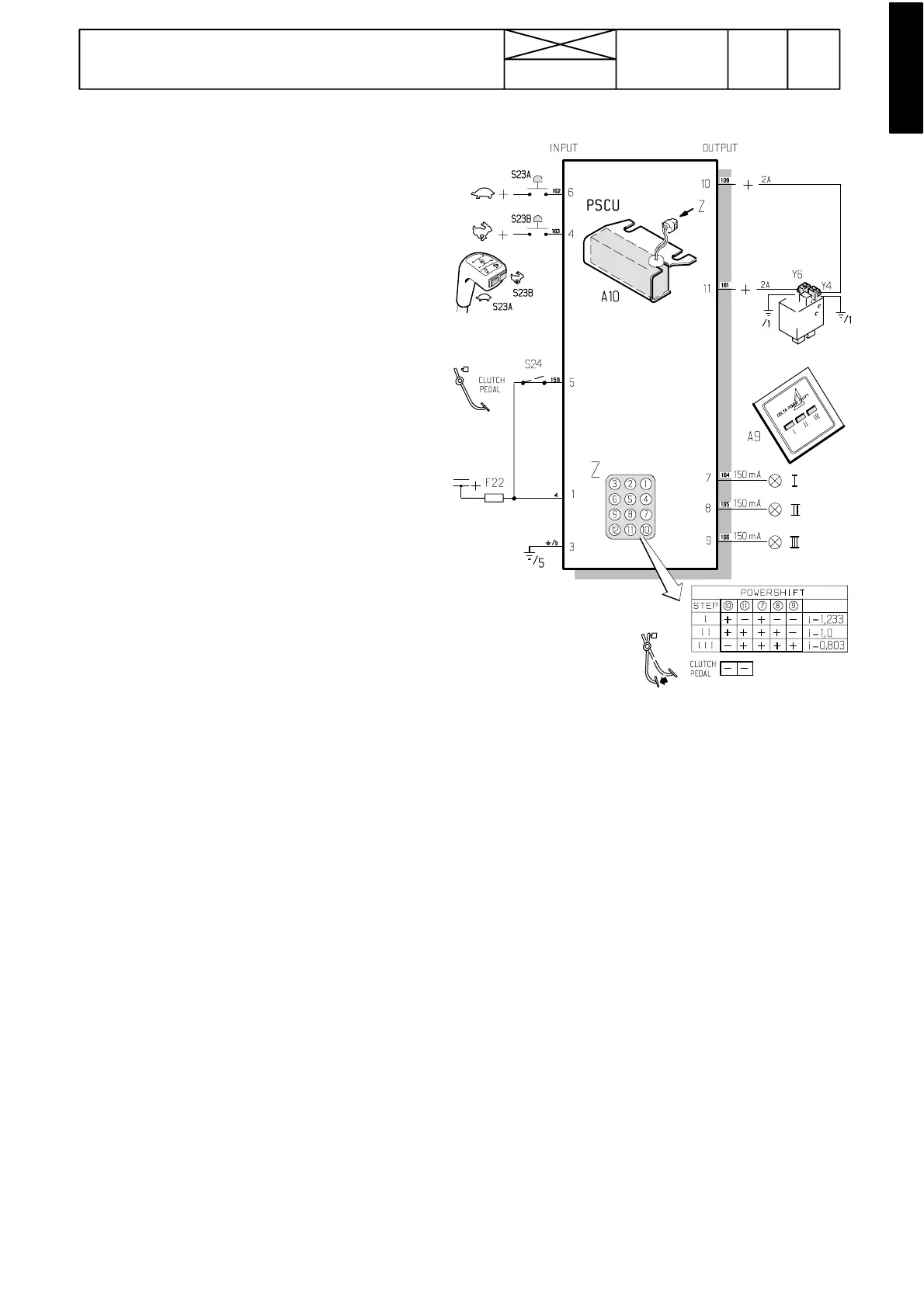
Picture 3. Input and output signals to the control unit A10. Sup-
ply voltage via the ignition switch and fuse F22.
Important! From trac tor ser. no. 668103 incl., th e control uni t
A10 has been modified, see Autocontrol 2.1 under code 312.
243
Model Code Page
31. Autocontrol II
1. 4. 1997
6000--8750 311 5
1. 1. 1994
A. Delta Powershift
Picture 2. Delta Powershift control.
1. Powershift control buttons:
S23A=change down
S23B=change up
2. Electronic control unit A10.
3. The circuit card A9 of the buzzer and the pilot lights. The
buzzer alarms if the engine is stopped (oil pressure sensor
S13 indicates whether the engine is running) and the parking
brake is not applied (the hand brake ind. light switch indicates
whether the hand brake is applied).
4. Valve block on which is fitted the solenoid valves (see also
page 440/13):
Y4=energised in reduction ratio = one ind. light
Y6=energised in overdrive=three ind. lights.
In the direct ratio both solenoid valves are energised=two ind
lights.
When the clutch pedal is depressed, the pedal switch S24 dis-
connects both solenoid valves to make gear change easier.
The switch must connect current to the control unit A10 when
the clutch pedal has raised 1,5--- 3 cm from the bottom posi-
tion.
The switch function can be tested by connecting a test lamp
to the wire from the switch (yellow wire no 159).
If you want remove the switch S24, disconnect both yellow
wires from the switch and connect them together with con-
nector SA1674.
Note! With effect from ser. no. F39513 the switch S24 has
been removed and the safety switch S9 has been transferred
to the support lower hole. On E ---models there is further switch
S24 and it is now fitted to the support upper hole.
Position of components:
--- Delta Powershift control unit A10 and its 12 pin connector
is fitted in the cab in front of the lever console. These are
accessibleafterremovingthepanelinfrontofthelever
console.
--- The push button connector S23 is situated in the same
place as above mentioned parts. Also connector X23 for
optional push buttons and 4WD switch connector S30 are
inthesameplace.
--- The circuit card of the buzzer and pilot lights are placed in
the instrument panel and they are accessible after remov-
ing the panel upper covering.
--- The solenoid valve connector X13 is placed under the
hand brake console on the driver’s left.