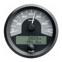
Product Manual CANcockpit
TU00-0726-5111102 Technische Änderungen vorbehalten 0609 Technical details subject to change 5.2 - 9
The reproduction, distribution and utilization of this document as well as the communication of its contents to others without express
authorization is prohibited. Offenders will be held liable for the payment of damages. All right reserved in the event of the grant of a patent,
utility model or design
.
CANopen-Specification for CANcockpit
Pre-Defined Connection Set
In order to reduce configuration effort for simple networks a mandatory default identifier allocation scheme is defined. These
identifiers are available in the PRE-OPERATIONAL state directly after initialization (if no modifications have been stored).
The default profile ID-allocation scheme consists of a functional part, which determines the object priority and a Node-ID-part,
which allows distinguishing between devices of the same functionality. This allows a peer-to-peer communication between a
single master device and up to 127 slave devices. It also supports the broadcasting of non-confirmed NMT-objects.
Broadcasting is indicated by a Node-ID of zero.
The pre-defined connection set supports one emergency object, one SDO, maximum 4 Receive-PDOs (RPDO) and 4
Transmit-PDOs (TPDO) and the NMT objects.
COB ID Structure of pre-defined Connection Set
Bit 10 9 8 7 6 5 4 3 2 1 0
F F F F N N N N N N N
Function Code Node ID
The following table outlines the CO allocation for the CAN controller.
CO Function Comment ID
1 TPDO1 64 Digital Inputs 0x0180+own Node ID
2 TPDO2
4 analogue Inputs
(ADC_wANI1Phy, ADC_wANI2Phy, ADC_wANI3Phy,
ADC_w20mAPhy)
0x0280+own Node ID
3 TPDO3
4 analogue Inputs (ADC_w5VPhy, ADC_wKl58, VN_wRevolution,
VN_wVelocity)
0x0380+own Node ID
4 Emergency Emergency Message and reserved for TNMT2025 0x0080+own Node ID
5 Heartbeat Heartbeat, also used for boot-up message. 0x0700+own Node ID
6 TSDO Send SDO responses 0x0580+own Node ID
7 RNMT0
Receive NMT commands with ID=0.
This CO will be serviced via interrupt.
0x0000
8
Reserved for
RNMT2026
Disabled until required.
9 RSDO Receive SDO messages 0x0600+own Node ID
10 RPDO1 64 Digital Outputs 0x0200+own Node ID
11 RPDO2 4 analogue Outputs (Main Gauge + 3Sat Gauges) 0x0300+own Node ID
12 RPDO3 4 analogue Outputs (4 Sat Gauges) 0x0400+own Node ID
13 RPDO4 4 analogue Outputs (4 Sat Gauges) 0x0500+own Node ID
14 RPDO5
4 analogue Outputs (4 Sat Gauges).
This PDO is not part of the pre-defined connection set. The system
designer must allocate a unique ID with WINgauge.
Configurable with
WINgauge
15 RPDO6
4 analogue Outputs (4 Sat Gauges).
This PDO is not part of the pre-defined connection set. The system
designer must allocate a unique ID with WINgauge.
Configurable with
WINgauge
16 RPDO7
4 analogue Outputs (4 Sat Gauges).
This PDO is not part of the pre-defined connection set. The system
designer must allocate a unique ID with WINgauge.
Configurable with
WINgauge

 Loading...