2.5.6.3.3 DTC List Display Format
One Graphic Symbol per DTC Channel (Source Address) can be configured and will be shown together with the DTC in the
upper and lower level. It indicates, where the DTC message comes from.
Also the number of received DTC`s on this channel (0-40) which are currently inside the DTC Ring Buffer will be displayed.
Examples:
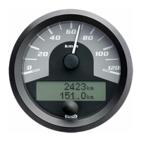
Electronic Engine Controller (EEC) reports Pre-Filter Oil Pressure
(SPN=1208) was 102 times (occurrence count) above normal operating
range - most severe level (FMI=0).
Index 10 provides information about the position inside the Ring Buffer.
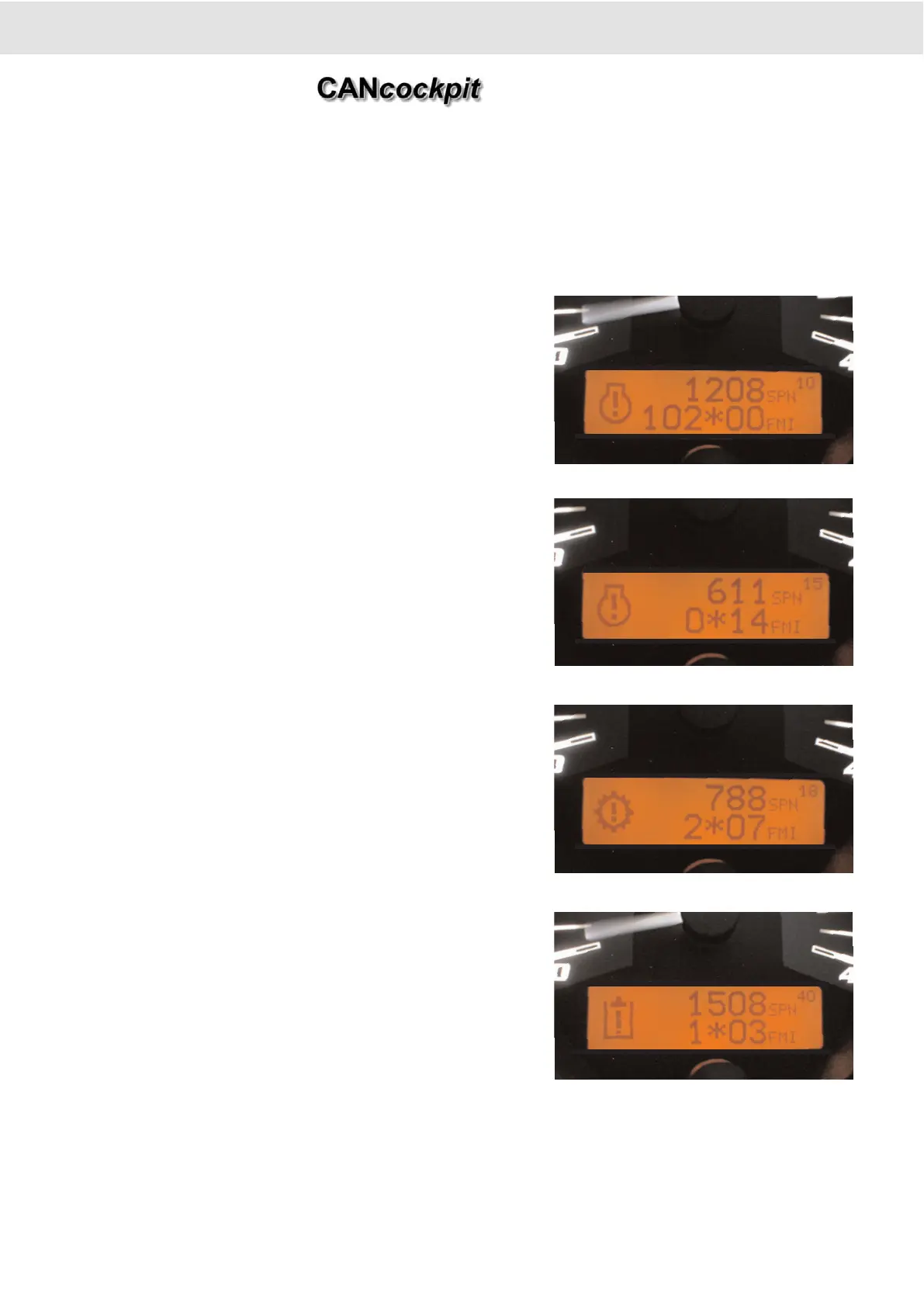
Electronic Engine Controller (EEC) reports System Diagnostic Code #1
(SPN=611), occurrence count information not available (OC=127) and
Special Instructions (FMI=14).
Index 15 provides information about the position inside the Ring Buffer.
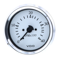
Electronic Transmission Controller (ETC) reports Clutch Actuator
(SPN=788) was 2 times Out of Adjustment ((FMI=7)
Index 18 provides information about the position inside the Ring Buffer.
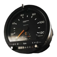
Hydraulic Controller reports Hydraulic Reservoir Temperature (SPN=1508)
one time Above Normal (FMI=3)
Index 40 provides information about the position inside the Ring Buffer.
2. Functional Specification
Product Manual
Technische Änderungen vorbehalten Technical details subject to change
2 - 24
TU00-0726-0000002
0609