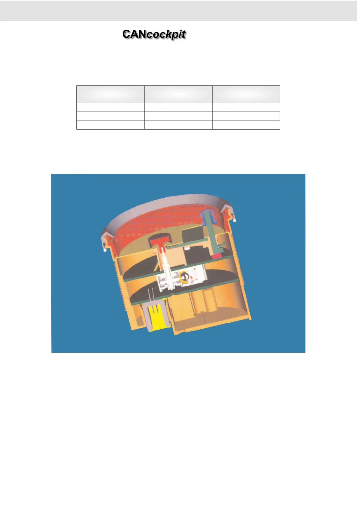
2.2 Mechanical Concept
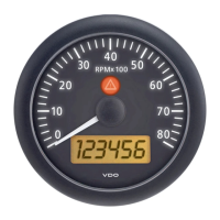
As the same LCD is used for different Master gauge diameters the pointer position has different eccentricities and indication
angles.
The connectors are 26-Pin MODU II-Connector and 4-Pin MATE-N-LOK from AMP.
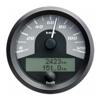
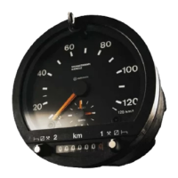
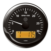
2.2.1 Master dia. 80 mm
Two PCB's are necessary for this diameter. They are connected with a standard pin connector
and two distance towers.
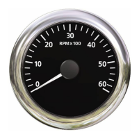
2.2.2 Master dia. 85 mm
The PCB assemblies and their corresponding parts of the Ø 80 mm and Ø 85 mm gauges are identical. The difference bet-
ween the two gauges is the position of the stepper motor on the PCB so that the eccentricity of 7 mm in the Ø 80 mm gauge
can be reduced to 4.5 mm in the Ø 85 mm gauge.
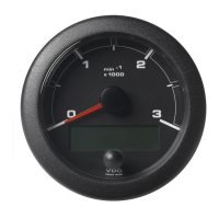
2.2.3 Master dia. 100 mm
For this size, only one PCB assembly is necessary. Input Signal Processing.
Gauge diameter [mm] Eccentricity [mm] Indication angle
80 7 210°
85 4.5 216°
100 0 206°
2. Functional Specification
Product Manual
Technische Änderungen vorbehalten Technical details subject to change
2 - 6
TU00-0726-0000002
0609