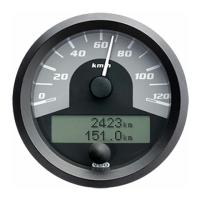
Product Manual CANcockpit
TU00-0726-5111102 Technische Änderungen vorbehalten 0609 Technical details subject to change 5.2 - 18
The reproduction, distribution and utilization of this document as well as the communication of its contents to others without express
authorization is prohibited. Offenders will be held liable for the payment of damages. All right reserved in the event of the grant of a patent,
utility model or design
.
CANopen-Specification for CANcockpit
2nd TPDO: 4 Analogue Inputs
Index Sub-Index Comment Value/ hex
1A01h 0 Number of mapped objects 4
1 Read Analogue Input 1 6401 01 10
2 Read Analogue Input 2 6401 02 10
3 Read Analogue Input 3 6401 03 10
4 Read Analogue Input 4 6401 04 10
3rd TPDO: 4 Analogue Inputs
Index Sub-Index Comment Value/ hex
1A02h 0 Number of mapped objects 4
1 Read Analogue Input 5 6401 05 10
2 Read Analogue Input 6 6401 06 10
3 Read Analogue Input 7 6401 07 10
4 Read Analogue Input 8 6401 08 10
Manufacturer Specific Profile Area
CANopen Display
Write display mode (2000h)
This variable controls the CANopen Display.
The following description is in a format based on CiA DS301: CANopen Application Layer and Communication Profile, Version
4.02
OBJECT DESCRIPTION
Index 2000h
Name Write display mode
Object Code VAR
Data Type UNSIGNED32
Category Optional
ENTRY DESCRIPTION
Access wo
PDO Mapping No
Value Range Coding and Value Range see below.
Default Value 0
Writing onto the LCD of the CANcockpit main gauge involves the following steps:
1. Write the desired texts via SDO as strings into the objects 2001h to 2003h. Keep in mind that the object 2003h
addresses the same internal memory as the objects 2001h and 2002h, but in a different format.
2. Activate the desired display by writing the display mode object. This also selects the corresponding graphic symbols.
As with all Alarms and Warnings the display can be configured to remain until it has been acknowledged or disappear as soon
as the relevant Bit-Signal (A) or (W) as described below becomes 0.
The UNSIGNED32 variable is defined as follows:
MSB LSB
Byte3 Byte2 Byte1 Byte0
See below for coding Reserved, set to 0. Index to Graphic Symbol
for Alarm
Index to Graphic Symbol for
Warning

 Loading...