Technische Änderungen vorbehalten Technical details subject to change
2 - 1
TU00-0736-0000002
0609
Contents
Contents
1. System 3
1.1 Main Features 3
1.1.1 Block Diagram CANcockpit 3
1.2 Mechanical Concept 3
1.3 Safety Concept 4
1.3.1 Sensors 4
1.3.2 System Check 4
1.3.3 Satbus 4
1.3.4 WINgauge 4
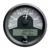
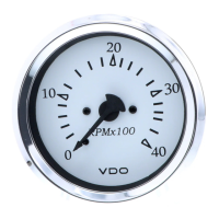
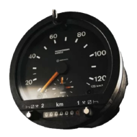
2. Master Gauges 5
2.1 General Features 5
2.1.1 Main Functions 5
2.2 Mechanical Concept 6
2.2.1 Master dia. 80 mm 6
2.2.2 Master dia. 85 mm 6
2.2.3 Master dia. 100 mm 6
2.3 Input Signal Processing 7
2.3.1 Analog Inputs 7
2.3.1.1 Grounding Concept 7
2.3.1.2 Sensors 7
2.3.2 Input Signal Processing applied to the two frequency inputs 7
2.3.3 Input Signal Processing for CANbus messages 8
2.4 PIN Assignment Description 9
2.4.1 Technical Description 9
2.5 Display Functions 12
2.5.1 Navigation through Display 12
2.5.2 Display Layout 12
2.5.3 Display Functions 14
2.5.3.1 Main Display (Odometer, Hourmeter) 14
2.5.3.2 Alarm Display 14
2.5.3.3 CAN DTC Display 15
2.5.3.4 Warning Display 15
2.5.3.5 Service Message 16
2.5.3.6 Physical Value Display 16
2.5.4 Alarm- and Warning Functions 17
2.5.4.1 Description of the Outputs 17
2.5.4.2 Switch Output Acknowledgement Function 17
2.5.4.3 Alarm and Warning Trigger Conditions 18
2.5.4.4 Alarm and Warning Trigger enabling with Engine running 18
2.5.4.5 Alarm and Warning State Diagram (Maximum Value Algorithm) 19
2. Functional Specification
Product Manual