Technische Änderungen vorbehalten Technical details subject to change
2 - 9
TU00-0726-0000002
0609
2.4 PIN Assignment Description
Master:
2.4.1 Technical Description
PIN 1: Power Supply (terminal 30)
V
Batt
= + 10,5 V to + 32 V
The instrument is supplied with permanent power through this terminal. Current consumption varies depending on the instru-
ments operating mode (standby or active) and number of Slaves.
PIN 2: Ground (terminal 31)
Power ground of the instrument.
PIN 3, 4: CANbus Interface 1
High-Speed Full CANbus V2.0B compatible (10, 20, 50, 125, 250, 500 kbit/s, 1 Mbit/sec.).
12 V and 24 V system compatible.
Cable: shielded, twisted pair with a drain.
Cable Impedance: nom. 120 Ω.
Topology: linear Bus
Trunk Length: max. 40 meters
Drop Length: max. 1 meter
Termination: 2 resistors 120 Ω at each end of the bus.
Related documents: ISO 11898, SAE J1939/11
U
A combination of 29 bit ID and 11 bit ID can`t be processed!
PIN 5, 6: CANbus Interface 2
See on CANbus Interface 1.
PIN 7: Not connected
PIN 8: K-Line Diagnostic Interface
Programming of the EEPROM and the diagnostics carried out via serial diagnostic interface K-Line.
PIN 9, 25: Analog Input 1
Range: 0.5 - 200
Ω
Standard sensors: Tube-type Sensor: 0,5 Ω to 90 Ω
Lever-type Sensor: 3 Ω to 180 Ω.
Sensor has to be connected between theese pins.
PIN 10, 25: Analog Input 2
2. Functional Specification
Product Manual
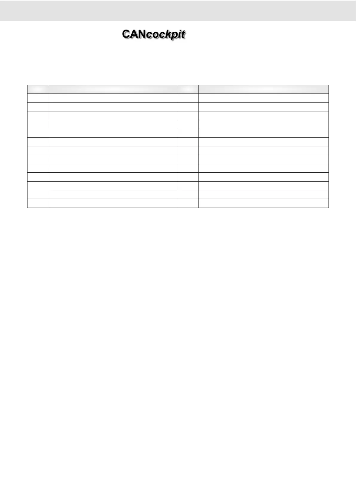
Pin Description Pin Description
1 Power Supply (terminal 30) 14 + 8 V DC for sensor supply
2 Ground (terminal 31) 15 0 - 5 V DC Input
3 CAN1 _High 16 Illumination (terminal 58 (d))
4 CAN1 _Low 17 Ignition (terminal 15)
5 CAN2 _High 18 Frequency Input 2 (0-2 kHz)
6 CAN2 _Low 19 Frequency Input 1 (0-40 kHz)
7 NC 20 Switch-Output_1
8 k-Line 21 Switch-Output_2
9
Analog Input 1 (0,5 - 200 Ω)
22 NC
10
Analog Input 2 (0,5 - 300 Ω)
23 NC
11
Analog Input 3 (10 - 700 Ω)
24 External Switch
12 4 - 20 mA Input 25 Analog GND
13 4 - 20 mA GND 26 Frequency GND