Do you have a question about the VDO CANcockpit Series and is the answer not in the manual?
Provides detailed instructions for installing the CANcockpit system, covering pre-installation, during installation, and post-installation steps.
Details the procedures and considerations for properly connecting the CANcockpit system's electrical components.
Describes the installation and connection of various sensors used with the CANcockpit system, including oil pressure and temperature sensors.
Outlines the general design concepts and features of the CANcockpit system, including CANbus interfaces and compatibility.
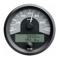
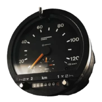
Details the mechanical design of the master gauges, including diameters, PCBs, and pointer mechanisms.
Explains how analog and frequency inputs are processed by the CANcockpit system, including grounding concepts.
Provides a detailed breakdown of the pin assignments for the master unit's connectors and their technical descriptions.
Describes the various display functions available on the master gauge, including navigation, layout, and specific display types.
Details the alarm and warning system, including input values, output functions, and trigger conditions.
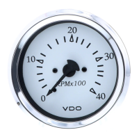
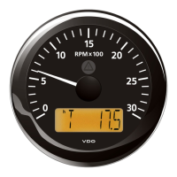
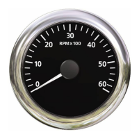
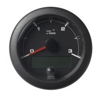
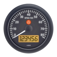
Explains the mechanical design of satellite gauges, including movements, connectors, and dial scales.
Describes the fault modes for satellite gauges, including pointer behavior when ignition is off or on.
Details the fixed address assignment for each satellite gauge and the matrix of gauge type and address combinations.
Describes the warning lamps within satellite gauges, noting that most are red except for amber level warning lamps.
Specifies the pointer accuracy tolerance for satellite gauges, which is ± 2.5%.
Specifies the operating and storage temperature ranges for the CANcockpit system, along with LCD visibility restrictions.
Details the nominal, operating, and test voltages for the CANcockpit system, including current consumption.
Describes the protection mechanisms for the CANcockpit's I/O circuits, including reversed battery polarity.
Specifies the required cable cross-sections for connections to the master and from the master to satellites.
Lists relevant SAE standards referenced in the CANcockpit documentation, such as J1226 and J1939.
Lists relevant European standards (e.g., DIN, EN, IEC) related to electromagnetic compatibility and vehicle components.
References enclosed documents related to installation, specifically mentioning 'Installation instructions'.
Details the main system components including master gauges, satellite gauges, and the master black box.
Lists available spare parts for the system, specifically detailing clamp rings for different gauge sizes.
Lists available accessories, including wiring harnesses for master-slave and slave-slave connections, and software accessories.
Provides a step-by-step guide to configuring the CANcockpit system using the WinGauge software.
Explains the use of the ICON Editor tool within WinGauge for creating and managing custom symbols and logos.
Details the hardware requirements for CANcockpit, including CANopen baud rates and identifiers.
Describes the different operational states of the CANcockpit system (Initialising, Pre-Operational, Operational, Stopped).
Outlines the minimum capabilities required for CANcockpit devices to ensure proper network functionality.
Defines the mandatory default identifier allocation scheme for simple CANopen networks.
Explains the structure and content of the CANcockpit's object dictionary, including message types and parameters.
Details the process for reading and writing data records to and from the CANcockpit's EEPROM via CANopen.
Describes the physical components of the master gauges, including housing, bezel, dial, and connections.
Provides technical specifications for master gauges, including voltage, current, EMC, and operating conditions.
Details the physical components and housing specifications of the Master Black Box.
Provides technical specifications for the Master Black Box, including voltage, current, and operating conditions.
Describes the physical components of the satellite gauges, including housing, bezel, dial, and connections.
Provides technical specifications for satellite gauges, including power supply, EMC, and operating conditions.
Details the connections and pin assignments for the K-line adapter used for diagnosis and programming.
| Brand | VDO |
|---|---|
| Model | CANcockpit Series |
| Category | Measuring Instruments |
| Language | English |