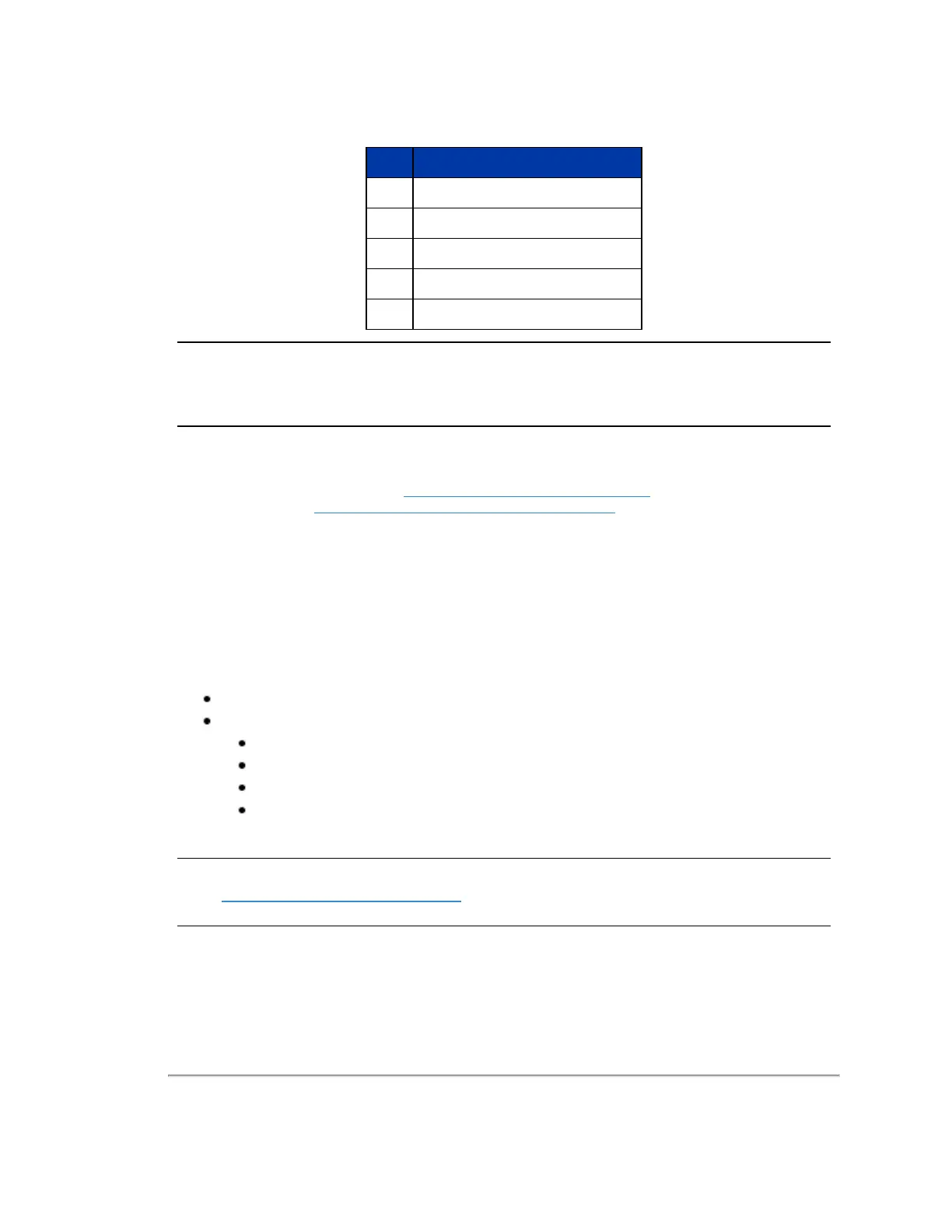
Item Description
1 Desktop/Laptop Computer
2 INS/GPS Antenna/Interface (optional)
3 Velodyne Interface Box
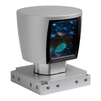
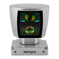
4 Velodyne LiDAR Sensor
5 DC Power Supply
Table 2-1 3D Sensing System Components
Note: Optional - not included unless ordered: Garmin GPS 18x LVC receiver (P/N: 80-GPS18LVC). When purchased
through Velodyne LiDAR, it comes pre-configured for use with any Velodyne sensors, making it a great reference GPS
receiver. Plugs directly into the Interface Box.
2.2 Product Models
For ordering information, contact Sales at http://www.velodynelidar.com/contacts.php. Data sheets for available models
can be downloaded from http://velodynelidar.com/downloads.html#datasheets.
2.3 Time of Flight
Velodyne LiDAR sensors use time-of-flight (ToF) methodology.
When each IR laser emits a laser pulse, its time-of-shooting and direction are registered. The laser pulse travels through
air until it hits an obstacle which reflects some of the energy. A portion of that energy is received by the paired IR detector,
which registers the time-of-acquisition and power received.
2.4 Data Interpretation Requirements
Desktop, Laptop or Embedded computer
Advanced geo-referencing software application
GPS-Based
SLAM-Based
User Built
Purchased from System Integrator
For more software details, see
Converting PCAP Files to Point Cloud Formats on page 69
.
Note: Click the following link to view a list of Velodyne system integrators who can sell you imaging software or a complete
system: http://velodyneLiDAR.com/integrators.php.
Chapter 2 • VLP-32C Overview 19

 Loading...