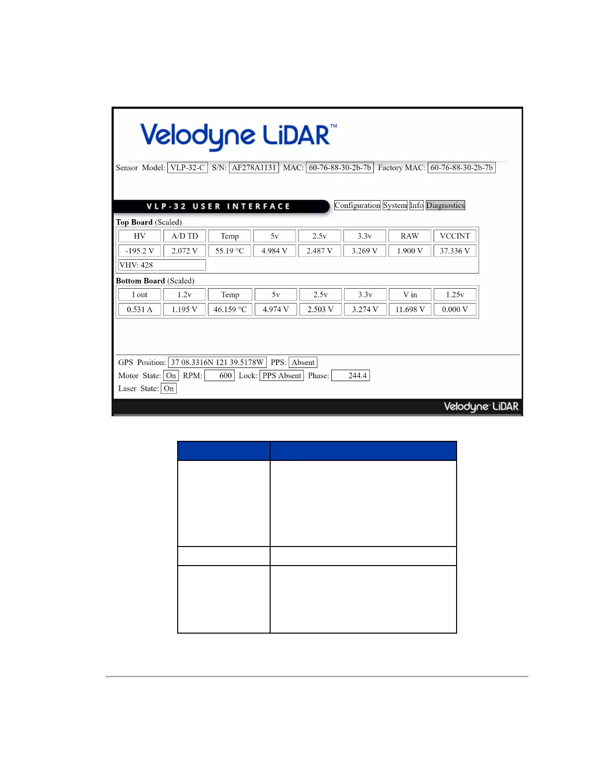
10.1.4 Diagnostics Screen
Figure 10-4 VLP-32C Diagnostics Screen
Function Description
Top Board (Scaled)
HV — Velodyne Use Only.
A/D TD — Velodyne Use Only.
Temp — Circuit board temperature.
5v — Internal voltage status.
2.5v — Internal voltage status.
3.3v — Internal voltage status.
RAW — Internal voltage status.
VCCINT — Internal voltage status.
VHV Velodyne Use Only.
Bottom Board (Scaled)
I out — The sensor's electrical current consumption.
1.2v — N/A.
Temp — Circuit board temperature.
5v — Internal voltage status.
2.5v — Internal voltage status.
3.3v — Internal voltage status.
Table 10-4 System Screen Functionality and Features
Chapter 10 • Sensor Communication 77

 Loading...