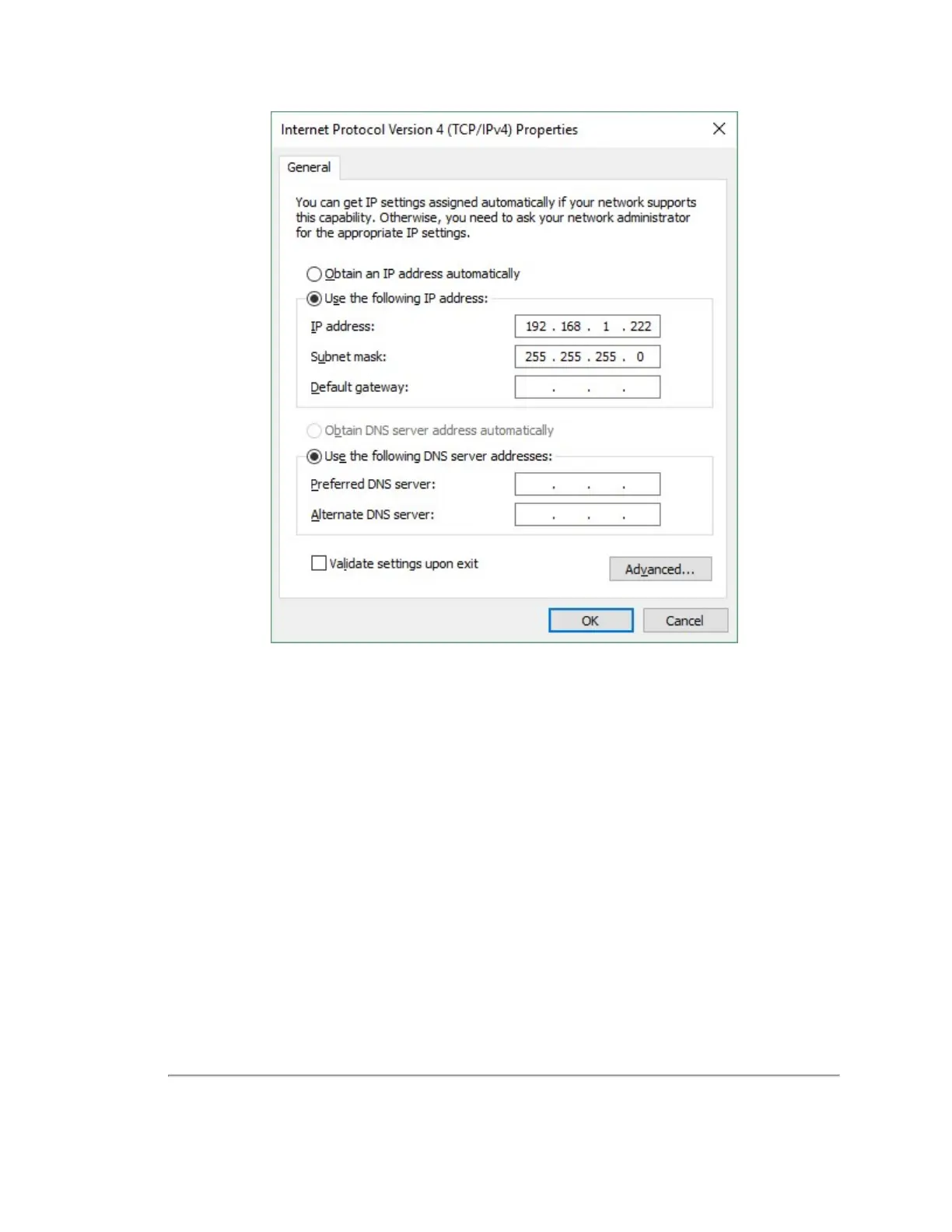
7. Click OK. Gateway and DNS are not necessary when testing in isolation.
In some cases it may be necessary to disable the computer’s firewall or configure it to allow UDP I/O on that Ethernet inter-
face. How to do this is not covered here as the process varies widely.
4.2.2 Access Sensor’s Web Interface
Now the computer is ready to connect to the sensor.
1. Plug the Ethernet cable into the computer and then plug its other end into the Ethernet port on the sensor’s Inter-
face Box.
Figure 4-2 below
shows the Interface Box, its external ports, internal sensor terminal, and fuse.
Figure 4-2 Interface Box (power and data connections)
24 VLP-32C User Manual

 Loading...