About connecting modules 3-19
Chapter 3: Setting Up the Wave IP 500 Server
Wave Server Installation Guide
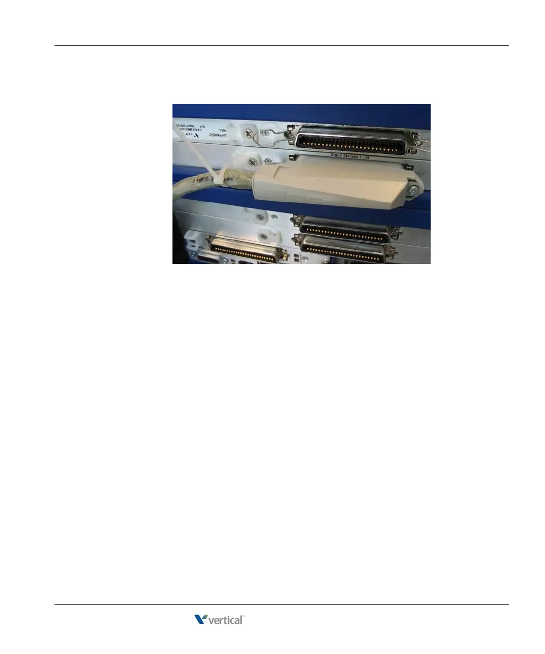
• 90° cable—The cable comes out of the side of the connector and then makes a 90°
turn.
You can connect a 90° cable on only one side using a screw. On the other side, use a
tie down on the module or card to secure the cable to the board with a tie wrap.
2. Make sure that the cables are securely connected. The tabs on modular connectors click
in when the cables are secure. Secure the cable to an RJ-21X connector with the cable
strap.
About connecting specific modules
See the following sections for information about connecting each of the supported modules:
• Analog trunk module. See page 3-20.
• Analog universal module. See page 3-20.
• Digital station module. See page 3-21.
• T1 module with serial interface. See page 3-22.
• E1 module with serial interface. See page page 3-23.
• Quad BRI module. See page 3-24.
Caution: Ensure that only analog phones are connected to analog station ports and only digital
phones to digital station ports. This will prevent damage to the analog circuitry.