6.1.2 Power Switch
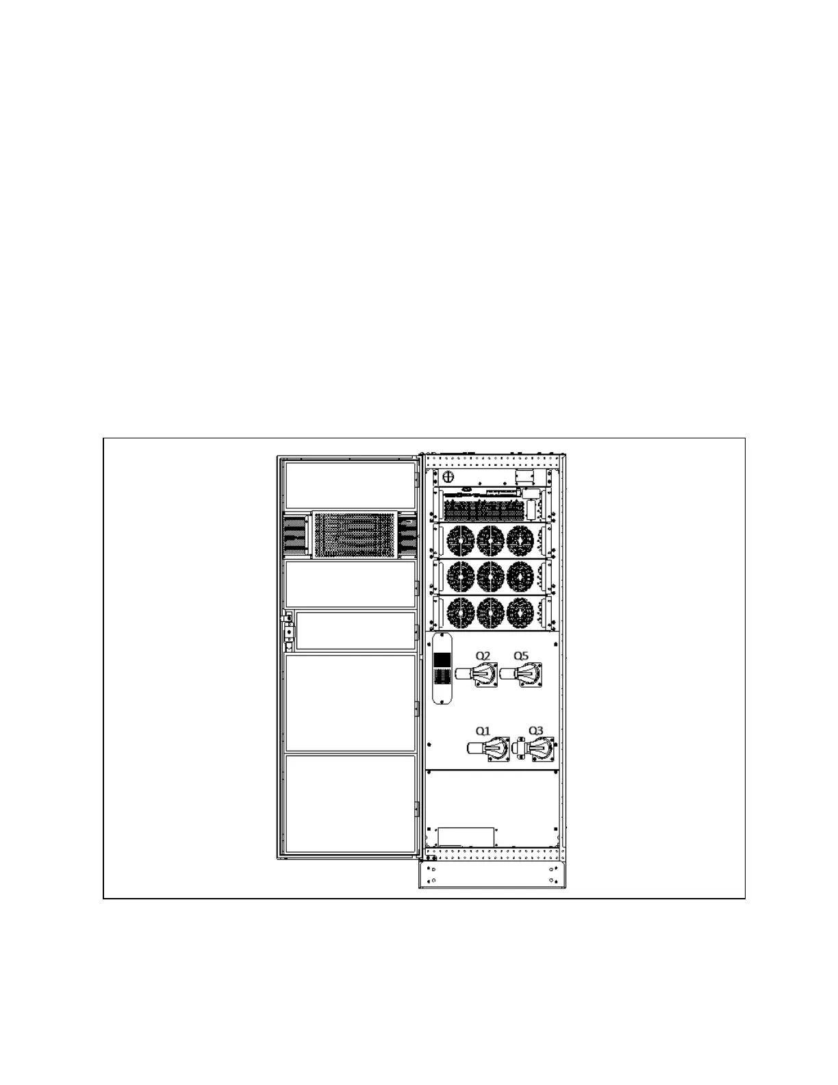
Opening the front door of the UPS cabinet reveals the power switches, as shown in Figure 6.1 below including:
Q1: Rectifier input switch, which connects UPS to the main circuit power.
Q2: Bypass input switch, which connects UPS to the bypass.
Q3: Maintenance bypass switch (With error-proof operation buckle), which supplies power to the load when UPS is being
maintained.
N O T E: If the UP S system consists of m ore than two paralleled UPS m o d u les, do not use the internal
m aintenance bypass switch.
Q5: Output switch, which connects UPS output to the load.
N O T E: Q 1, Q 2, and Q 5 are optional while Q 3 is stan d ard.
Figure 6.1 U PS power switch
10 0 kVA ~ 160kVA
6 Single UPS Operation Introduction
104
Vertiv™ Liebert® EXM2 UPS User Manual