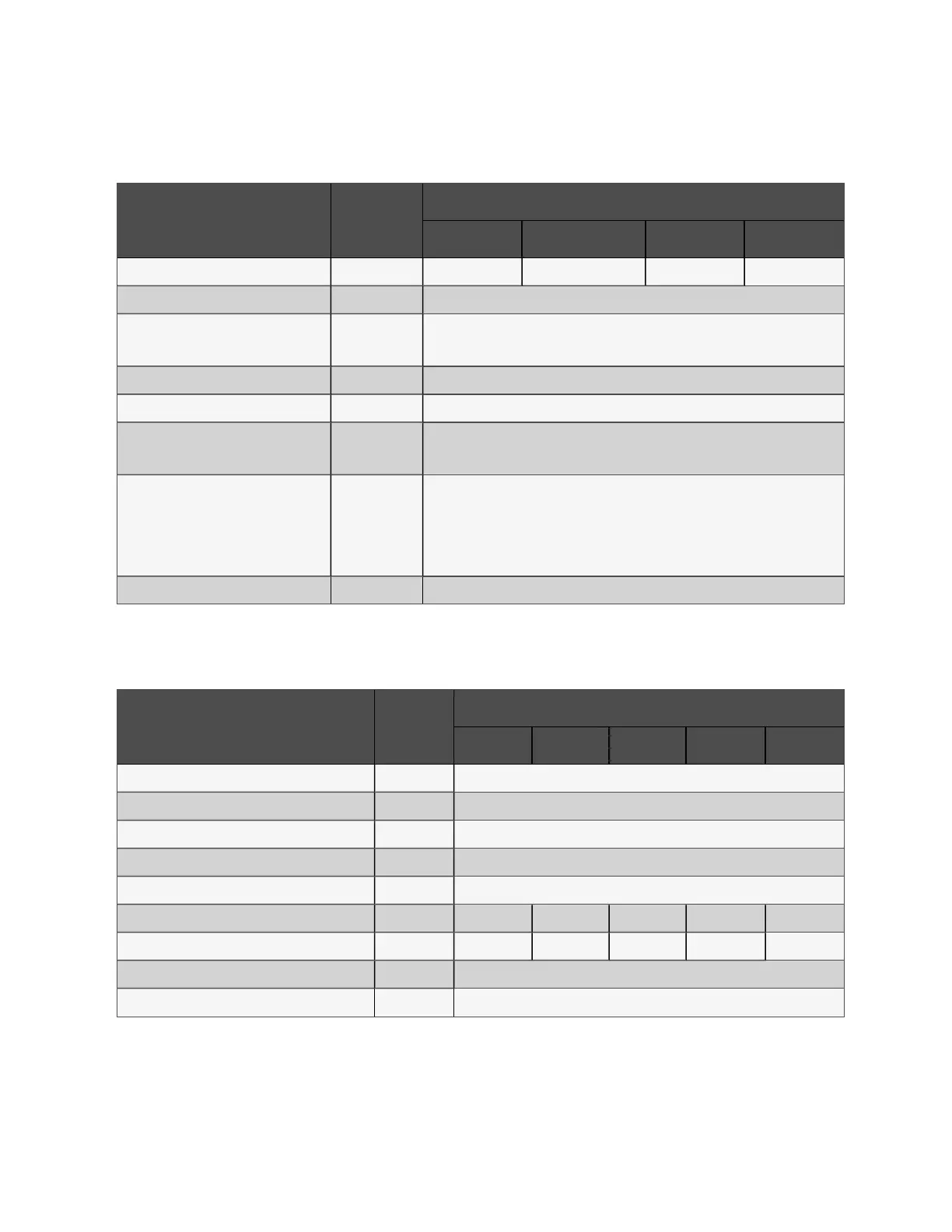
12.5 Electrical Characteristics (Intermediate DC Circuit)
Item U nit
Ra ted po wer (kV A)
100 12 0/150/160 20 0 25 0
Max. charging current A 30 45 60 75
Quantity of lead-acid cells (nominal) Block 28 ~ 44 (12Vdc)
Float voltage V/cell (VRLA)
2.25 (selectable from 2.2V/cell to 2.3V/cell)
Constant current and constant voltage charge mode
Temperature compensation mV/°C/cl -3.0 (selectable from 0 to -5.0 around 25°C or 30°C, or inhibit)
Ripple current % C
10
≤ 5
Boost voltage V/cell (VRLA)
2.35 (selectable from 2.3 to 2.35)
Constant current and constant voltage charge mode
Boost control
Float-boost current trigger 0.050C
10
(selectable from 0.001 to 0.070)
Boost-float current trigger 0.010C
10
(selectable from 0.001 to 0.025)
8hr safety time timeout (selectable from 8hr to 30hr)
Boost mode inhibit also selectable
EOD voltage V/cell (VRLA) 1.67
Table 12.5 Battery
12.6 Electrical Characteristics (Inverter Output)
Item Unit
Ra ted po wer (kV A)
100 12 0 16 0 200 2 50
Rated AC voltage
1
Vac 380/400/415 (3-phase 4-wire, with neutral reference to the bypass neutral)
Frequency
2
Hz 50/60
Power factor 1
Overload % <105%, long time; <110%, ≤1hr; <125, ≤10min; <150, ≤1min; >150, ≤200ms
Max. short circuit current of inverter A Up to 240% for 200 ms
Three phase no neutral short circuit current A
RMS
292 448 448 584 730
Single phase to neutral short circuit current A
RMS
388 550 550 733 920
Non-linear load capability
3
kVA 100
Steady state voltage stability % ±1
Table 12.6 Inverter output (to critical load)
12 Specifications
185
Vertiv™ Liebert® EXM2 UPS User Manual