4.2.3 Dry Contact Port J7
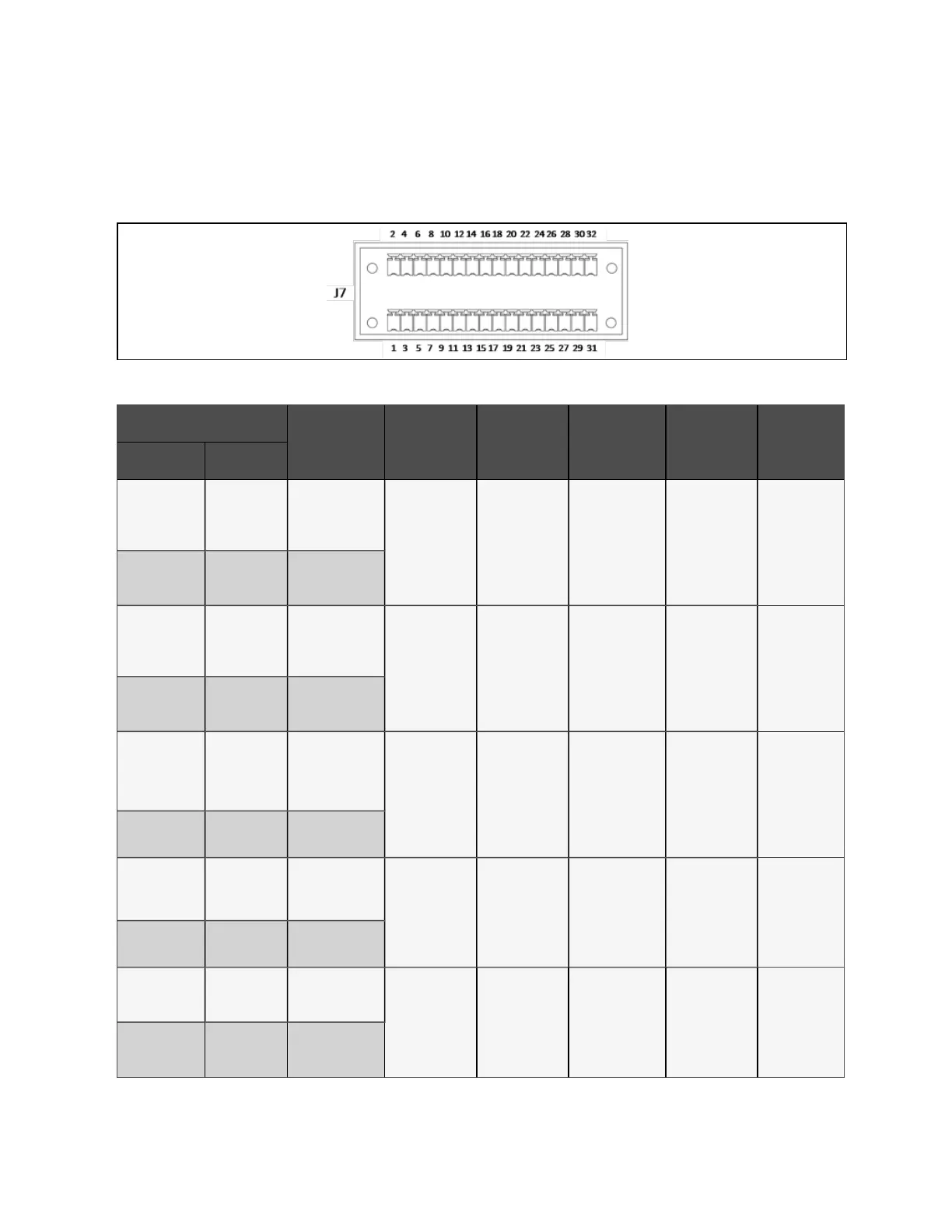
The dry contact port J7 is shown in Figure 4.6 below and described in Table 4.6 below.
Figure 4.6 Dry contact port J7
Term in al Designation
Signal N am e
M axim um
Voltage
M axim um
Curren t
W ire Rang e
M axim um
Length
Re m arks
Fro m To
J7-1
Q1 Ext (Input
Switch)_STATUS
24 VDC 10 mA 16-22 AWG 30 m
External Input
switch status
(24 V/ 10 mA
rated);
Pin1/Pin3
shorted for Q1
EXT closed
J7-3 GND_DRY
J7_5
Q2 Ext (Bypass
Switch)_STATUS
24 VDC 10 mA 16-22 AWG 30 m
External Bypass
switch status
(24 V/10 mA
rated);
Pin5/Pin7
shorted for Q2
EXT closed
J7_7 GND_DRY
J7_9
QBP
(Maintainenace
Switch)_STATUS
24 VDC 10 mA 16-22 AWG 30 m
External
Maintenance
switch status
(24 V/10 mA
rated);
Pin9/Pin11 open
for QBP closed
J7_11 GND_DRY
J7_13
QE (Output
Switch)_STATUS
24 VDC 10 mA 16-22 AWG 30 m
Output switch
status (24 V/10
mA rated);
Pin13 /Pin15
shorted for QE
closed
J7_15 GND_DRY
J7_2 GEN_MODE
24 VDC 10 mA 16-22 AWG 30 m
Generator
Mode;
Pin2/Pin4
shorted for
generator
connected.
J7_4 GND_DRY
Table 4 .6 Description of dry contact port J7
4 Electrical Installation
48
Vertiv™ Liebert® EXM2 UPS User Manual