9.2.19 Transformer
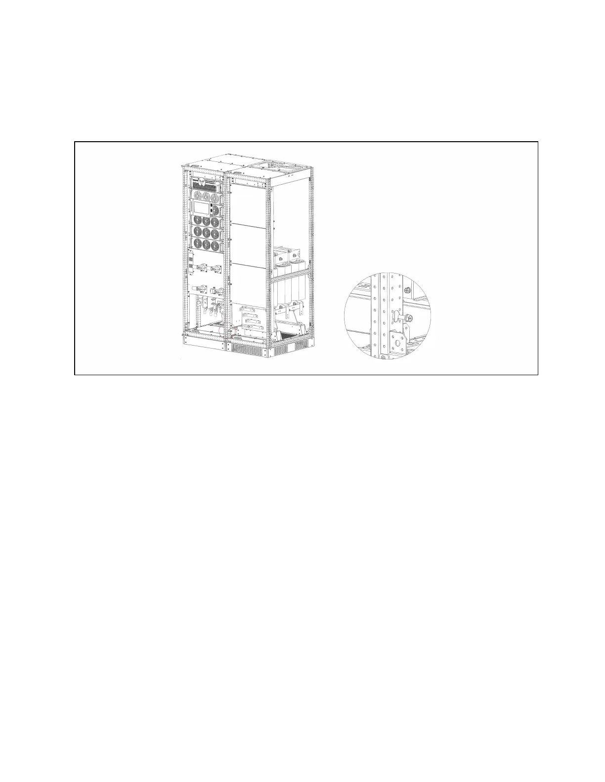
As shown in Figure 9.16 below, connect the UPS main cabinet and transformer cabinet in parallel using screws.
Figure 9.16 Parallel cabinet w ith transformer
Connect the power cable of the transformer cabinet to the output OA\OB\OC\ON\PE terminals shown in Figure 4.2 on
page40. The signal cables of the transformer cabinet are routed to the corresponding terminals on the host board X3.
After the transformer options are selected, the user load cables need to be connected to the transformer cabinet
OA\OB\OC\ON\PE terminals shown in Figure 9.17 on the next page.
9 Options
171
Vertiv™ Liebert® EXM2 UPS User Manual