N O T E: T he m o d u le will be blocked by a sp ring p iece on the right sid e of the m odule when the m odule
is pulled out of the cabinet halfw ay. A t this point, you m ust p ress th e sp ring piece before you
continue to pull the m odule ou t.
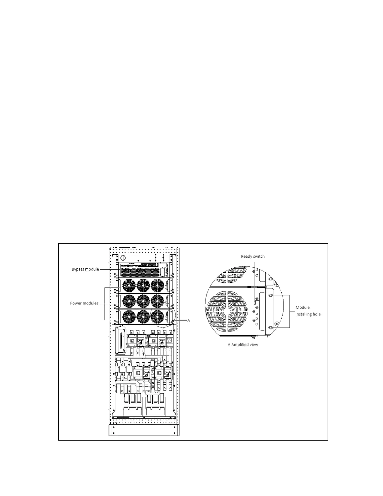
6. Check that the ready switch is in unready state before inserting the power module.
7. Push the module (at least 10s after another) into the cabinet, and tighten the screws on both sides. Then press
the ready switch.
8. Power on the UPS as per the normal procedures.
11.2.2 Service Procedures of Bypass Module
Provided that the UPS is in normal mode, and that the bypass is normal:
1. Manually turn off the inverters, and the UPS transfers to bypass mode.
2. Close the maintenance bypass, and the UPS transfers to maintenance mode.
3. Press the EPO button, ensure that the battery current is less than 2A. Open the BCB or disconnect the batteries.
4. Remove the fixing screws on both sides of the front panel of the bypass module, and pull the module out of the
cabinet. Wait for 10 minutes before servicing the bypass module.
5. After servicing the module, push the module (at least 10s after another) into the cabinet, and tighten the screws
on both sides, and place the ready switch to unready state.
6. Power on the UPS as per the normal procedures.
Figure 11.1 Installing pow er m odules of 100 kV A ~ 160kVA
11 Service and Maintenance
178
Vertiv™ Liebert® EXM2 UPS User Manual