4.1.4 Selection of UPS I/O and Battery Switch
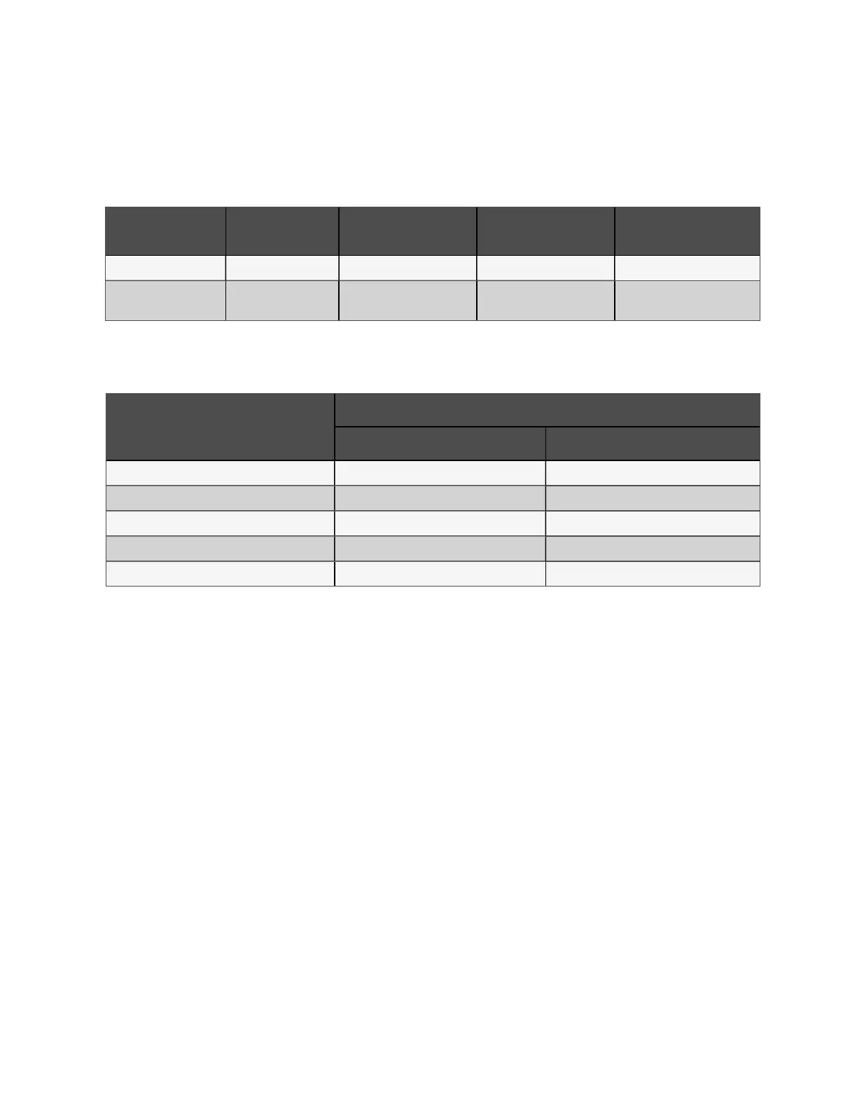
The user can select the switch according to actual needs. Table 4.3 below shows inbuilt switch assembly capacitiesTable 4.3
below
M od el
Re ctifier inp ut
sw itch (optional)
By pass input sw itch
(op tional)
O utput sw itch (optiona l)
M ainte nan ce b ypass switch
(stan dard )
100-160 kVA Input ( 315 A) Bypass input (315 A) Output (315 A, 4P) Maintenance bypass (315 A)
200-250 kVA
500 A (3P), isolating
switch
500 A (3P), isolation switch 400 A (4P), isolating switch 400 A (3P), isolating switch
Table 4 .3 In built UP S I/O sw itch capacity
4.1.5 Distance Between the UPS Connection Point and The Floor
UPS co nnection po in t
M in. d is tanc e (m m )
100 kV A to 16 0k VA 20 0k VA to 250k VA
Rectifier input 366 348
Bypass input 366 387
AC Output 388 371
Battery supply 360 425
PE terminal 352 510
Table 4 .4 M in. d istance b etween U PS connection point and floor
4.1.6 Notes
The following points are for general guidance only. If there are relevant local regulations, the local regulations shall prevail.
1. The cable size of the protective earth cable shall be selected according to the AC power failure level, cable
length and protection type. The grounding wire connection must use the shortest connection route.
2. For the cables with large current, parallel connection of small cables can be adopted to facilitate the installation.
3. When selecting the battery cable size, the current value in Table 4.1 on the previous page shall be referred to,
and a maximum voltage drop of 4Vdc is allowed.
4. Do not form coils, so as to minimize the formation of EMI.
4.1.7 Power Cable Connecting Terminal
The rectifier input, bypass input, output and battery power cables are connected to the corresponding terminals shown in
Figure 4.2 on page40.
4 Electrical Installation
37
Vertiv™ Liebert® EXM2 UPS User Manual