9.2.10 IS-Relay Card
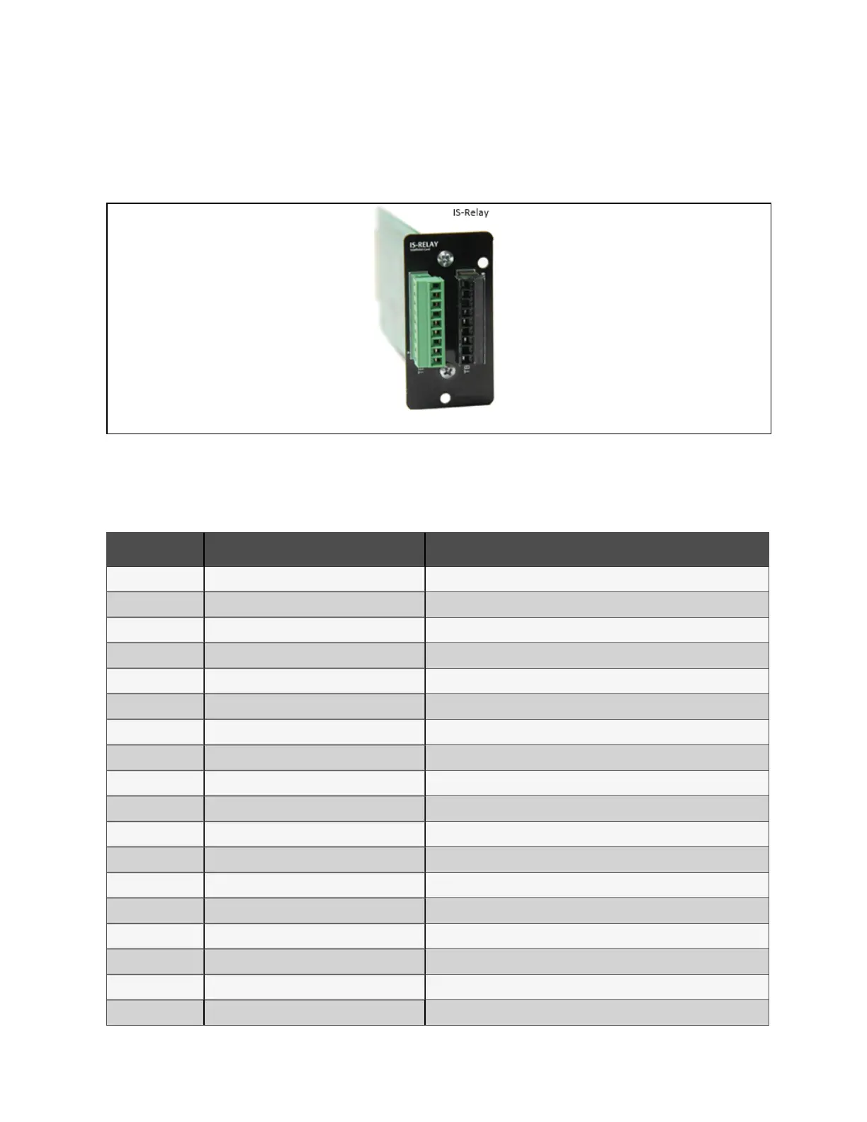
The appearance of the IS-Relay card is shown in Figure 9.10 below.
Figure 9.10 A ppearance of IS-R elay card
The UPS provides IS-Relay card for the user to use the dry contact signal to monitor the UPS.
The functions of the IS-Relay card are listed in Table 9.3 below.
Pin Func tion O peration
1 Common-Low Battery
2 Low Battery Closed if low battery point occurs
3 Low Battery Closed if battery is OK
4 Common-UPS Fault
5 UPS Fault Closed if UPS fault occurs
6 UPS Fault Closed if no UPS failure
7 Common-On Battery
8 On Battery Closed if On Battery power (Utility failure)
9 On Battery Closed if not On Battery power (Utility OK)
10 Signal Ground Future release
11 Signal Ground Future release
12 UPS Any-Mode Shutdown Future release
13 Summary Alarm Closed if no alarm conditions are present
14 Summary Alarm Closed if summary alarm occurs
15 Common-Summary Alarm
16 On UPS Closed if On UPS (inverter) power
17 On Bypass Closed if On Bypass
18 Common-On Bypass
Table 9 .3 Fun ctio n of UPS IS-Relay card
9 Options
165
Vertiv™ Liebert® EXM2 UPS User Manual