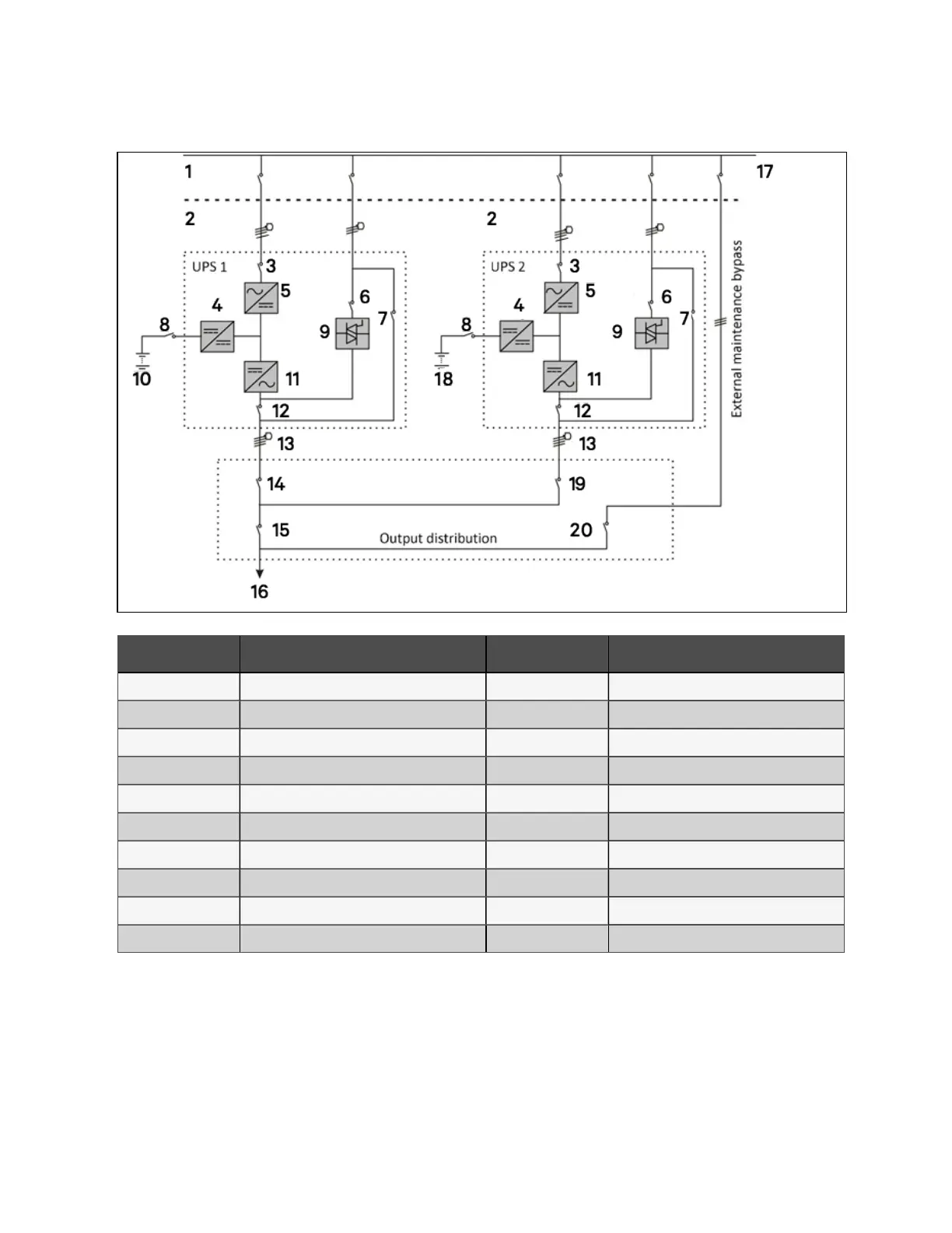
Figure 8.1 Schem atic of typ ical parallel system (w ith comm on input, separate b atteries an d output)
N O. Des cription N O. Des cription
1 Input power supply 11 Inverter
2 Mains input L1, L2, L3, N 12 Q5
3 Q1 13 L1, L2, L3, N
4 Charger 14 Q1EXT
5 Rectifier 15 QOP
6 Q2 16 TO load
7 Q3 17 External bypass switch
8 BCB 18 Battery 2
9 Static switch 19 Q2EXT
10 Battery 1 20 QBP
N O T E: Q 1, Q 2 and Q 5 are optional while Q 3 is stand ard
8 Parallel System and LBS System
140
Vertiv™ Liebert® EXM2 UPS User Manual