Vertiv | SmartCabinet | User Manual 14
System Installation
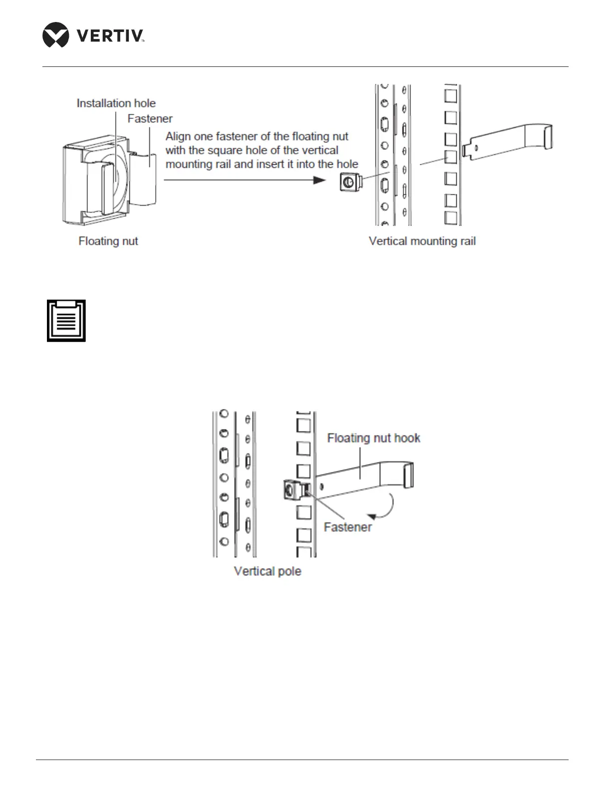
Figure 2-2 Schematic diagram 1 for installing oating nut
• The oating nut should be inserted into the square hole in the horizontal direction, i.e. the fasteners
on both sides of the oating nut should touch the left and right sides of the square hole. The fasteners
should not touch the top and bottom of the square hole.
2. Lead the oating nut through the square hole. Hitch the other fastener of the oating nut and pull it out to
x the fastener to the square hole completely as shown in Figure 2-3.
Figure 2-3 Schematic diagram 2 for installing oating nut
Fittings
The utilities used for ttings are shown in the following Figure 2-4.