Vertiv | SmartCabinet | User Manual 46
System Installation
Connecting the MSC Intelligent monitoring card cables
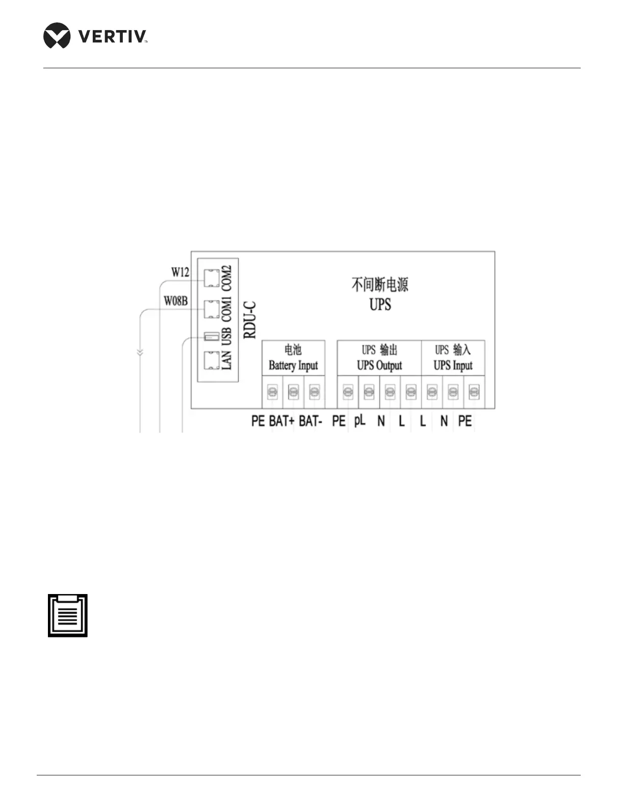
Connect the two communication network cables at the back of the intelligent card slot on the rear panel of
the UPS to their corresponding ports of the MSC intelligent monitoring card.
• Connect the cable W08B to the COM1 port of the MSC-C card.
• Connect the cable W12 to the COM2 port of the MSC-C card.
The connections are shown in Figure 2-36:
Figure 2-36 Cable connections of the COM port of the MSC intelligent monitoring cards
Connecting the Total input cables of the system
Prior to connection, remember that the total input cables (length, size and quantity) needs to be user-
prepared, based on the installation position of the SmartCabinet. Comply with the local regulations and
protocols. Also, consider the environment and refer to the global table as per the IEC60950-industry
standard Table 3B. Vertiv recommends that the minimal CSA of selected cables must be 6mm2 and the
external total input air breaker is large than or equal to 50A.
• The UPS is a large current leakage device; therefore, it’s recommended that a residual current operat-
ed circuit breaker should not be congured.
Following is the procedure or set of steps for connecting the total input cables:
1. Press and connect the OT Terminal (an accessory) on the cable end.
2. Open the cover plate on the back of the PMU followed by connecting the prepared cable to the total input
position of the PMU connecting terminal block as shown in Figure 2-37.