Document: LT0344 Vigilant MX1 Operator Manual
Issue 2.4 8 August 2017 Page 1-5
Office
Factory
Garage
Shed
Shop
Vigilant MX1
Sample MX1 Site Name
MX1 V1.60 AS 7240.2 05:40:47
Normal
11/02/15
Alphanumeric Liquid Crystal
Display (LCD)
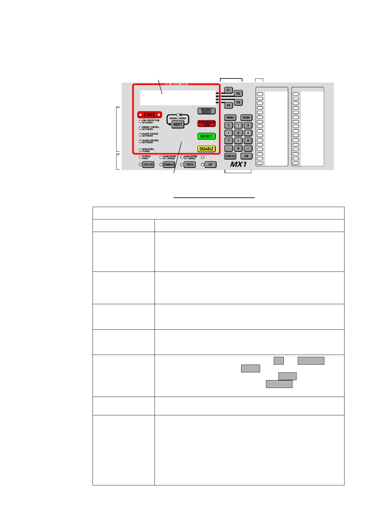
Fire Brigade Panel
(FBP)
Soft Keys
Status
Indicators
Numeric
Keypad
Zone LED
Indicators
Fire
Brigade
Panel
Indicators
Fig 1-1 – Operator Interface
Table 1-1. Components of the Operator Interface
Alphanumeric
Liquid Crystal
Display (LCD)
Displays details about alarms, faults, and other service-related
system information, as well as menus of command options and
messages.
The information normally displayed in the LCD, without operator
intervention, is called the “base display”.
Fire Brigade Panel
(f.b.p.)
Controls and indicators within the red border are for use by fire
brigade personnel during alarm attendance. See the quick
reference guide at the front of the manual, or page 2-2 for more
detail.
These keys have different functions, depending on the current
display. Each key’s function at any time is shown by the text
displayed at the right side of the LCD.
LED indicators showing the presence of faults, disabled items,
tests in progress and power status. The associated keys provide
a direct way to display this information.
Numeric keys, plus commonly used keys: OK and CANCEL, to
confirm or cancel commands, MENU to display the current
possible actions on the item displayed, and ZONE to provide
direct access to zone functions. Press CANCEL once to move
back one display, or press and hold to return to the base display.
The top row of the zone LEDs shows the Common Fire (red),
Defect (Fault – yellow) and Normal (green) LEDs.
Zone LED
Indicators (optional)
These show the state of individual zones or groups of zones.
A flashing red indicator is an alarm,
A steady red indicator shows operated, or if the zone is
disabled a disabled alarm or operate state,
a flashing yellow indicator is a fault,
a steady yellow indicator shows a disabled zone.
These indicators may also be configured to convey non-alarm
statuses.