Document: LT0344 Vigilant MX1 Operator Manual
Issue 2.4 8 August 2017 Page 8-5
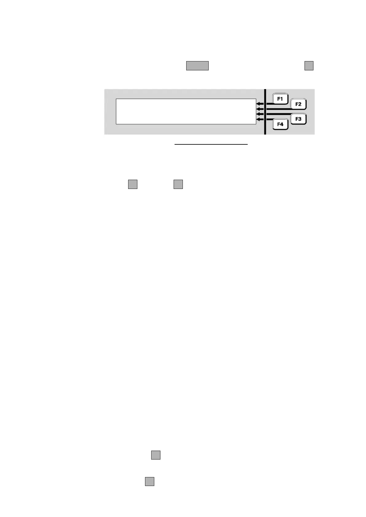
From the base display press MENU three times then MX LOOPF2 to
view the MX Loop Status.
Equipment : 8 Ver 2.00 |
MX Loop : 40.7V, 0.0A | PREV
Return : 40.3V | NEXT
| DEVICES
Fig 8-5 –
MX
Loop Status
Equipment: shows which MX loop is being viewed. 1 is the on-
board loop and 2 onwards are the optional MX Loop Cards. The
firmware version for each MX Loop Card will be included. Press
PREVF2 or NEXTF3 to switch between loops.
MX Loop: is the voltage and current being fed to the loop wiring.
Return: the voltage at the return end of the loop.
Normally the power is fed via the AL terminals and the loop return
voltage is measured at the AR terminals. In this situation the points
described below will all be normal.
Under fault conditions, the power feed may be switched to the AR end
(for a short circuit at the AL terminals), or feed via both ends (for an open
circuit in the loop, or a short circuit between two short circuit isolators).
Fig 8.5 shows a typical situation. The power feed is applied to the start
of the loop, which is drawing only a light load current. The voltage at the
end of the loop is being monitored to detect any breaks in the wiring.
If power is being fed to the AR side, the Return voltage displayed will be
0V. If the loop is drawing too much current, the MX Loop voltage display
will also be 0V. A more detailed assessment of the MX Loop condition
can be gained from the presence of these points in the fault list (refer to
Chapter 11 (“Equipment Point Descriptions”) for details).
MX Loop Left S/C – is in Fault if there is a short circuit between
the AL+ and AL- terminals.
MX Loop Right S/C – is in Fault if there is a short circuit between
the AR+ and AR- terminals.
MX Loop Open Circuit – is in Fault if there is an open circuit in
the loop wiring. Note that an activated short circuit isolator will also
register as an open circuit fault.
MX Loop Overload – is in Fault if too much current is being drawn
by the MX Loop. The normal capacity for each loop is 1A.
Press IR CTRLF1 to access the Infrared commands. Note this
command requires operator Access Level 2.
The DEVICESF4 command allows the loop to be scanned for all MX