EasyManua.ls Logo

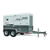
Wacker Neuson G 240

Wacker Neuson G 240
254 pages
To Next Page IconTo Next Page
Loading...
5000186930 09 0215
5000186930
Operator’s Manual
Mobile Generator
G 230
G 240
EN

Table of Contents

Other manuals for Wacker Neuson G 240

Questions and Answers:

Wacker Neuson G 240 Specifications

General IconGeneral
BrandWacker Neuson
ModelG 240
CategoryInverter
LanguageEnglish

Summary

Machine Identification

Serial Number (SN)

Record serial number for future reference, parts, and service.

Safety Information

Signal Words Used in this Manual

Explains hazard signal words (DANGER, WARNING, CAUTION, NOTICE, NOTE).

Machine Description and Intended Use

Details the generator's purpose and proper usage to avoid damage or injury.

Safety Guidelines for Operating the Machine

Covers operator training, qualifications, application area, and safety devices.

Service Safety

Outlines precautions and requirements for machine servicing and maintenance.

Operator Safety while Using Internal Combustion Engines

Covers safe engine operation, fueling, and exhaust hazards.

Safety Guidelines for Mobile Generators

Addresses generator-specific hazards like carbon monoxide and electrocution.

Safety Guidelines for Towing the Machine

Provides essential checks and practices for safely towing the machine.

Safety Guidelines for Lifting the Machine

Details safe procedures and requirements for lifting the generator.

Label Locations

Label Meanings

Explains the meaning of various warning and information labels on the machine.

Lifting and Transporting

Lifting the Machine

Provides requirements and procedures for safely lifting the generator.

Before Towing Checklist

Comprehensive checklist for trailer and towing vehicle preparation.

Towing the Machine

Covers towing safety, licensing, and coupler maintenance.

Preparing the Machine for Transport on a Truck or Trailer

Checklist for securing the machine for transportation.

Testing the Breakaway System (Hydraulic Surge Brakes)

Procedure for testing the hydraulic surge brake breakaway system.

Testing the Breakaway System (Electric Brakes)

Procedure for testing the electric brake breakaway system.

Machine Setup

Preparing the Machine for First Use

Steps to follow before operating the machine for the first time.

Positioning the Machine

Guidelines for placing the machine in a safe and stable operating location.

Grounding the Generator

Explains grounding procedures for safety and electrical compliance.

Recommended Fuel

Details appropriate fuel types and additives for different ambient temperatures.

Refueling the Machine (Basler Controller)

Step-by-step instructions for refueling using the Basler controller.

Refueling the Machine (Deep Sea Controller)

Step-by-step instructions for refueling using the Deep Sea controller.

Operation, Control, and Component Locations

Control Component Locations

Identifies and describes the location of various controls and components.

Operation (Basler Controller)

Main Circuit Breaker

Explains the function and location of the main circuit breaker.

Engine Start Switch

Describes the engine start switch positions and their functions.

Genset Pre-Alarms and Alarms (Shut-Down Conditions)

Details pre-alarm and alarm conditions and how to reset them.

Selecting the Voltage

Explains the process for selecting and fine-tuning the generator voltage.

Starting and Running the Generator

Step-by-step procedure for starting and operating the generator.

Emergency Stop Switch

Explains the function and proper use of the emergency stop switch.

LCD Panel: Monitoring Machine Operation

Details how to read and interpret information on the LCD panel.

Working with Basler Controller

How to Use the Genset Controller LCD and Keypad

Explains the basic operation of the LCD and keypad for navigation.

Menu Diagram of the Genset Controller

Visual guide to the genset controller's menu structure and navigation.

Logging in to the Genset Controller by Entering the Password

Procedure for logging into the controller using a password.

Adjusting the LCD Screen Contrast

Steps to adjust the brightness and contrast of the LCD screen.

Changing the Low Fuel Pre-Alarm Setting

How to adjust the fuel level threshold for pre-alarm warnings.

Changing or Disabling the Low Fuel Alarm Setting

How to modify or disable the low fuel level alarm shutdown.

Resetting the Maintenance Interval Pre-Alarm

How to clear the maintenance interval pre-alarm indicator.

Operation (Deep Sea Controller)

Main Circuit Breaker

Explains the function and location of the main circuit breaker.

Selecting the Voltage

Explains the process for selecting and fine-tuning the generator voltage.

Deep Sea Controller ButtonsFunctions

Details the function of each button and indicator on the Deep Sea controller.

Genset Controller Alarms and Shut-Down Conditions

Covers warning alarms, shut-down alarms, and electrical trips.

Starting and Running the Generator

Step-by-step procedure for starting and operating the generator.

Emergency Stop Switch

Explains the function and proper use of the emergency stop switch.

Working with Deep Sea Controller: DSE 7310

Introduction

Overview of the DSE 7310 controller's capabilities and operation.

Navigating the Menus

Guide to navigating through the controller's menus and options.

Adjusting Screen Contrast

Steps to adjust the brightness and contrast of the LCD display.

How to Connect Loads

Lug Terminal Connection Diagrams

Diagrams showing how to connect loads using lug terminals.

Best Practices for Balancing Loads

Guidance on distributing loads evenly across generator phases.

Connecting 480 V, 3-Phase and Single-Phase Loads

Instructions for connecting high-voltage loads to the generator.

Connecting a 240 V 3 Load and a 240 V 1 Load

Steps for connecting 240V three-phase and single-phase loads.

Connecting a 220-240 V 3 Load and Multiple 127-133 V 1 Loads

Instructions for connecting mixed voltage and phase loads.

Using Remote Start Capabilities

Remote Run Terminal Block

Describes the terminal block for connecting remote start/transfer switches.

Preparing for AutomaticRemote Start-Up (Basler)

Steps to prepare the generator for remote start with a Basler controller.

Preparing for AutomaticRemote Start-Up (Deep Sea)

Steps to prepare the generator for remote start with a Deep Sea controller.

Diagnostic Trouble Codes (DTC)

Accessing DTCs with the Basler Controller

How to retrieve diagnostic trouble codes from the Basler controller.

Accessing Engine DTCs using the Deep Sea Controller

How to retrieve diagnostic trouble codes from the Deep Sea controller.

List of Engine Diagnostic Trouble Codes (DTCs)

A comprehensive list of engine diagnostic trouble codes and their meanings.

Factory-Installed Options

Battery Charger

Information on the optional battery charger for maintaining battery power.

Lockable Battery Disconnect

Description of the lockable switch for disconnecting the battery.

Containment System

Explains the function of the containment system for capturing leaks.

Extended Run Tank (ERT)

Information about the optional extended run tank for longer operation.

Low Coolant Shutdown

Explains the system that monitors coolant level and shuts down the engine.

Positive Air Shutoff Valve

Explains the function of the positive air shutoff valve for runaway engines.

Quick-Disconnect Fuel Fittings

Instructions for connecting an external fuel supply using quick-disconnect fittings.

Lube Level Maintainer

Description of the system that maintains engine oil levels.

Machines with Aftertreatment Exhaust System

How the Aftertreatment Exhaust System Works

Explains the components and operation of the emission control system.

Filling the DEF Tank

Step-by-step procedure for filling the Diesel Exhaust Fluid (DEF) tank.

Monitoring and Control of the DEF Level

How the genset controller monitors DEF levels and displays messages.

Conditioning the Aftertreatment Exhaust System (if equipped)

Procedure for manually conditioning the SCR system to burn DEF crystals.

General Maintenance

Periodic Maintenance Schedule

A table outlining basic maintenance tasks and their recommended intervals.

Preparing for Maintenance

Checklist for safely preparing the machine before performing maintenance.

Cleaning the Machine

Instructions for cleaning the interior and exterior of the machine.

Inspecting the Machine

Daily checks for external and internal inspection of the machine.

Maintaining the Trailer

Maintenance procedures for tires, wheels, axle hubs, and brakes.

Checking and Draining the Containment System

Procedure for checking and draining the fluid containment system.

Maintaining the Battery

Safety precautions, connections, and maintenance for the battery.

Filling the Radiator

Step-by-step instructions for filling the radiator with coolant.

Replacing the Aftertreatment DEF Dosing Unit Filter

Procedure for replacing the DEF dosing unit filter.

Storage

Procedures for preparing the machine for extended storage.

Machine Disposal Decommissioning

Guidelines for safely preparing and disposing of the machine.

Engine Maintenance: John Deere 4045 TF285 HF285 6068 HF285

Engine Maintenance: T4 i Cummins QSB6.7

Engine Maintenance: T4 F Cummins QSB7-G9

Technical Data - G 240

Engine

Engine specifications including make, model, displacement, and power rating.

Generator

Generator specifications including type, voltage, frequency, and output.

Trailer and Skid

Specifications for the trailer and skid, including weight and dimensions.

Dimensions

Physical dimensions of the G 240 model.

Technical Data - G 230

Engine: G 230 T4 f

Engine specifications for the G 230 T4f model.

Engine: G 230 T4 i

Engine specifications for the G 230 T4i model.

Generator

Generator specifications including type, voltage, frequency, and output.

Trailer and Skid

Specifications for the trailer and skid, including weight and dimensions.

Dimensions

Physical dimensions of the G 230 model.

Tire Safety Information

Introduction to Tire Safety Information

Overview of tire safety information requirements and topics.

1. TIRE SAFETY INFORMATION

General information and regulations regarding tire safety.

1.2. STEPS FOR DETERMINING CORRECT LOAD LIMIT - TOW VEHICLE

Steps to correctly determine and manage load limits for towing.

1.5. SAFETY FIRST-BASIC TIRE MAINTENANCE

Covers basic tire maintenance principles and safety tips.

1.5.4. STEPS FOR MAINTAINING PROPER TIRE PRESSURE

Detailed steps for checking and adjusting tire pressure.

1.5.6. TIRE TREAD

Information on checking tire tread depth and replacement indicators.

1.5.9. TIRE FUNDAMENTALS

Information on standardized tire markings and safety standards.

1.5.9.1. Information on Passenger Vehicle Tires

Explanation of tire sidewall markings for passenger vehicles.

1.5.9.3. Additional Information on Light Truck Tires

Specific tire markings and information relevant to light truck tires.

Emission Control Systems Information and Warranty-Diesel

Introduction

Overview of EPA and CARB regulations for emissions control systems.

24.3 Limited Defect Warranty for Wacker Neuson Emission Control Systems

Details the warranty period and coverage for Wacker Neuson emission controls.

Owners Warranty Responsibility

Outlines the owner's responsibilities regarding maintenance and warranty claims.

How to Make a Claim

Instructions on how to submit a warranty claim for emission-related parts.

General Machine Schematics

Fuses

Diagrams showing the location and rating of fuses for various models.

Trailer Wiring

Wiring diagrams for standard, hydraulic, and electric trailer brakes.

Trailer Wiring Components

Lists and describes the components used in trailer wiring.

Schematics, Machines with Basler Controller

AC Schematic: G 230 G 240

AC schematic diagram for the G 230/G 240 models with Basler controller.

AC Schematic Components: G 230 G 240

Lists and describes the components shown in the AC schematic.

DC Schematic: G 240 John Deere Tier 3

DC schematic diagram for G 240 John Deere Tier 3 model.

DC Schematic Components: G 240 Tier 3

Lists and describes components for the G 240 Tier 3 DC schematic.

DC Schematic: G230 Cummins T4 i

DC schematic diagram for the G230 Cummins T4i model.

DC Schematic Components: G 230 T4 i

Lists and describes components for the G 230 T4i DC schematic.

DC Electrical Schematic Section A: G 230 Cummins T4 f

DC schematic diagram section A for G 230 Cummins T4f model.

DC Electrical Schematic Components

Lists and describes components for the DC electrical schematic.

DC Electrical Schematic Section B: G 230 Cummins T4 f

DC schematic diagram section B for G 230 Cummins T4f model.

DC Electrical Schematic Section C: G 230 Cummins T4 f

DC schematic diagram section C for G 230 Cummins T4f model.

Cummins Engine Relays and Fuses

Diagrams and lists of Cummins engine relays and fuses.

Schematics, Machines with Deep Sea Controller

AC Schematic: G 230 G 240

AC schematic diagram for G 230 / G 240 models with Deep Sea controller.

AC Schematic Components: G 230 G 240

Lists and describes components for the AC schematic.

DC Schematic: G 240 John Deere Tier 3

DC schematic diagram for G 240 John Deere Tier 3 model.

DC Schematic Components: G 240 John Deere Tier 3

Lists and describes components for the G 240 Tier 3 DC schematic.

DC Electrical Schematic Section A: G 230 Cummins T4 f

DC schematic diagram section A for G 230 Cummins T4f model.

DC Electrical Schematic Section B: G 230 Cummins T4 f

DC schematic diagram section B for G 230 Cummins T4f model.

DC Electrical Schematic Section C: G 230 Cummins T4 f

DC schematic diagram section C for G 230 Cummins T4f model.

Cummins Engine Relays and Fuses

Diagrams and lists of Cummins engine relays and fuses for Deep Sea controller.