G 230 / G 240 Schematics, Machines with Deep Sea Controller
wc_tx003750gb_FM10.fm
245
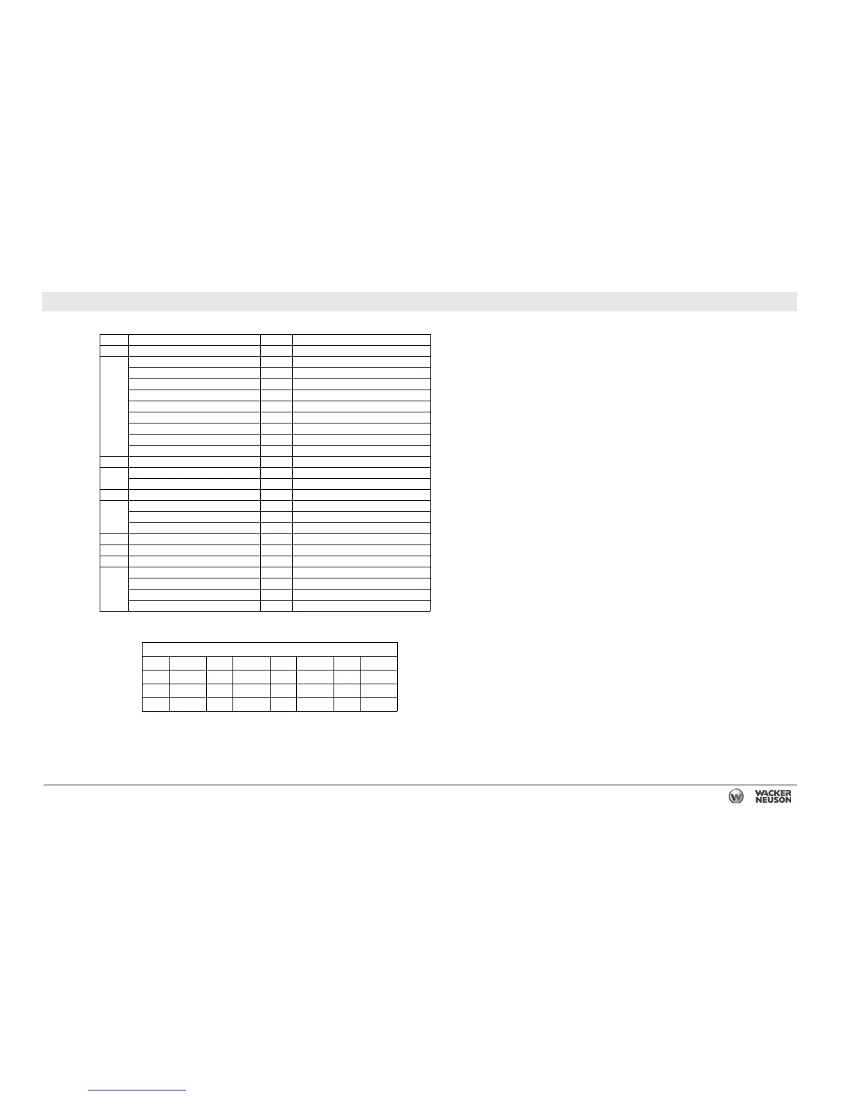
27.10 Electrical Schematic Components
Ref. Description Ref. Description
1 Plug 1 - power and engine sender inputs 7 Genset power toggle switch
Battery - 8 Hour meter
Battery + 9 30A fuse
Fuel 10 10A fuse
Start 11 10A fuse
Ground 12 5A fuse
Regeneration light 13 7.5A fuse
Alarm 18 Emergency stop switch
Prealarm 19 Remote start terminals
Trip breaker 22 Shunt
2 Plug 2 - contact inputs 23 Mechanical lugs
Sender communication 24 Main circuit breaker
Fuel level 25 Fuel level sender
3 Plug 3 - canbus 26 Lug door interlock switch
Canbus low 27 Bond bar
Canbus high 28 Shunt trip relay
Selective Catalyst Reduction (SCR) 33 Terminal strip
4 Electronic control unit (genset controller) 49 Manual conditioning toggle switch
5 Idle toggle switch 50 Light (manual regeneration)
6 Plug 6 - contact inputs 53 Telematics unit
Remote suction 54 5A fuse
Breaker tripped — —
Idle — —
Regeneration — —
Wire Colors
BK Black RD Red YL Yellow OR Orange
GN Green TN Tan BR Brown PU Purple
BU Blue VIO Violet CL Clear SH Shield
PK Pink WH White GY Gray LB Lt. blue